
On-the-go soil sensors and control methods for agricultural machines

Active Publication Date: 2014-10-09
LEADER TECH
View PDF7 Cites 87 Cited by
  • Summary
  • Abstract
  • Description
  • Claims
  • Application Information

AI Technical Summary

Benefits of technology

The present invention aims to improve the state of the art by improving yield by promoting uniform seed germination and plant emergence, and by providing a control system to adjust planting depth based on soil moisture or seed to soil contact. This results in a more efficient and effective planting process.

Problems solved by technology

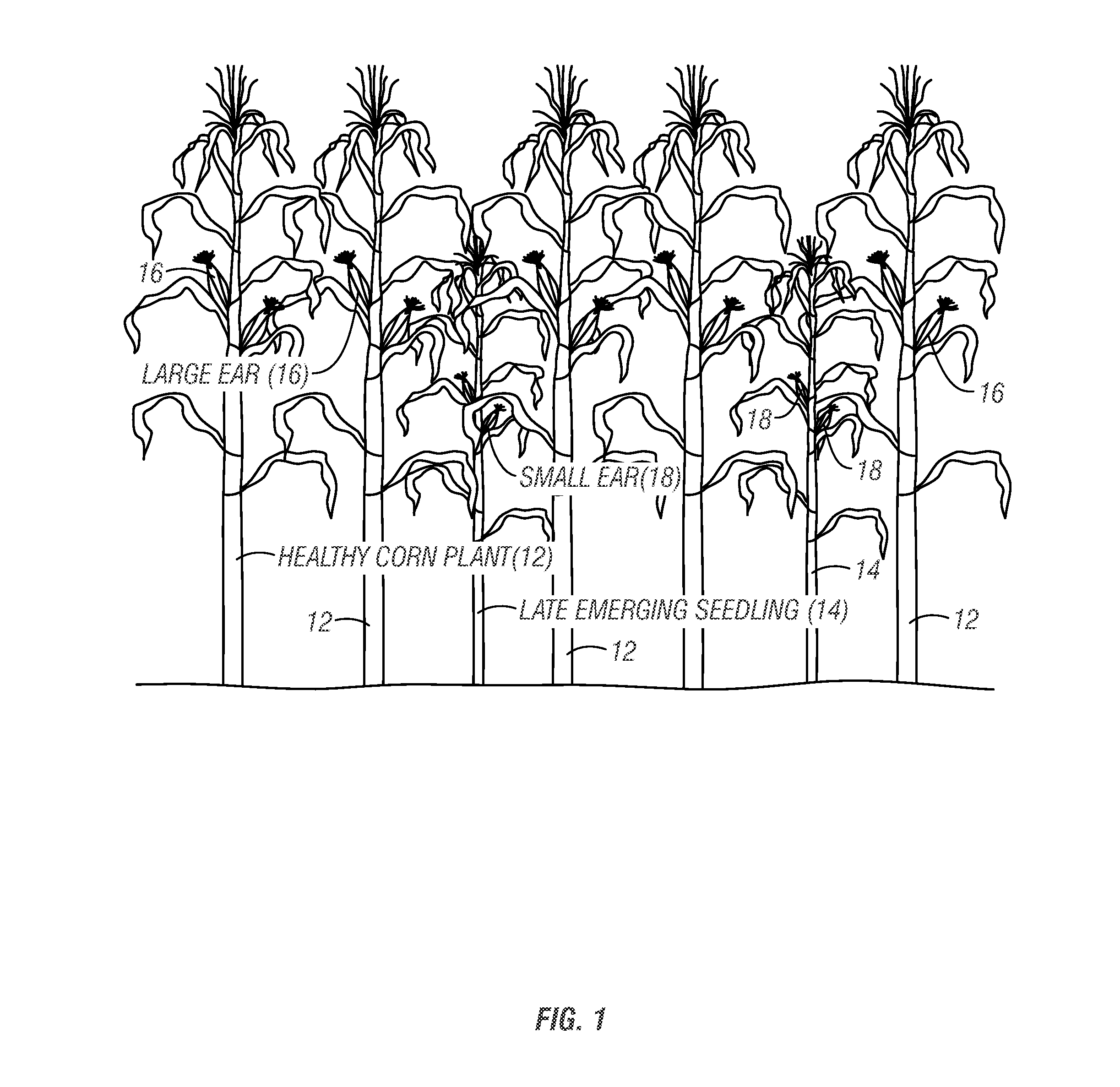
Healthy corn plants, on the other hand, are not very effective at recapturing yield lost by nearby stunted plants.
Historically in corn production, more attention has been put on achieving uniform spacing than uniform emergence; however, recent research shows that “uneven emergence has a greater adverse effect on yield than uneven spacing” according to Exapta article Uniform timing of emergence trumps uniform spacing for yield effect.
Therefore, delayed germination means delayed plant emergence.
The “seed firmer” tool can improve seed germination by improving seed to soil contact in loose soil, but it can lose its effectiveness when soil voids caused by clods at the bottom of seed trench occur.
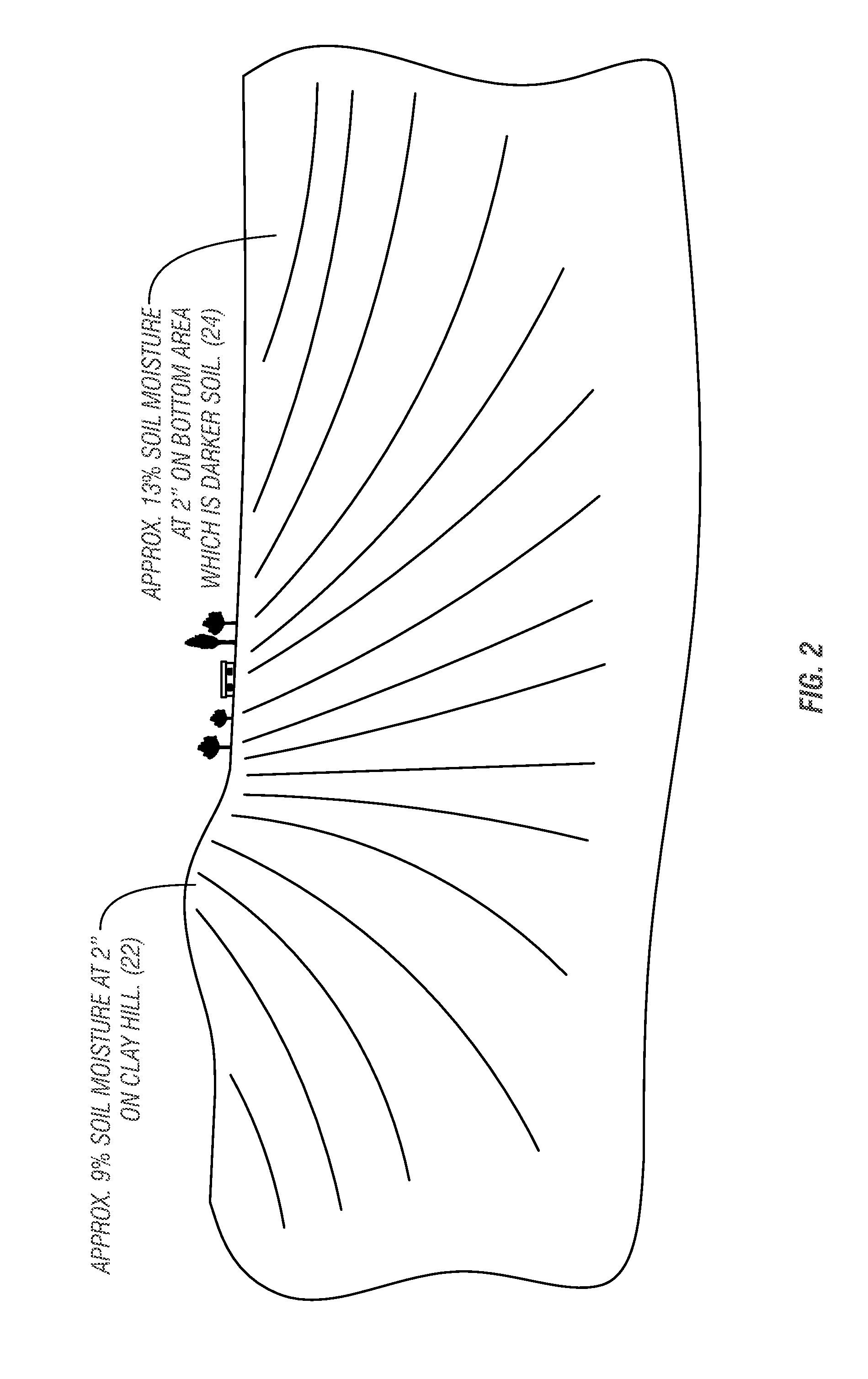
Uneven soil moisture throughout the seed zone is a primary cause of uneven germination and emergence, the results of which can be yield loss.
Calculating the overall soil moisture level of a field prior to planting is difficult, as soil moisture varies throughout the field and depends on several factors such as topography, weather conditions, tillage patterns, soil profile, and uneven seeding depth.
Thus, it is extremely difficult to determine the overall level of moisture in a field prior to planting.
As a result, few farmers use soil moisture meters to set planting depths as they lack confidence in the soil moisture reading to achieve synchronous seed germination throughout a field.
This age-old technique is largely based on past planting experience and is obviously subject to human error.
In addition, the number of samples tends to be very limited in size.
The bottom line is farmers do not have a good means to account for inconsistent soil moisture levels throughout a field during planting.
On-the-go soil moisture sensors generally are not commercially available despite a few examples utilized in research venues.
Tilling soil too wet causes soil compaction which restricts root growth and can reduce yield.
Gauge wheel load sensors are known in the art to sense when the row unit is cutting a seed trench at the intended depth; however, they don't account for the depth error from plant residue and they can't measure the magnitude of the depth of cut of the seed trench.

Method used


Image

  • On-the-go soil sensors and control methods for agricultural machines
  • On-the-go soil sensors and control methods for agricultural machines
  • On-the-go soil sensors and control methods for agricultural machines

Examples


Embodiment Construction

[0052]The present invention includes systems and methods for use in adjusting seed planting depth and row unit down pressure to account for varying levels of soil moisture in a field when planting to minimize occurrences of late emerging corn seedlings.

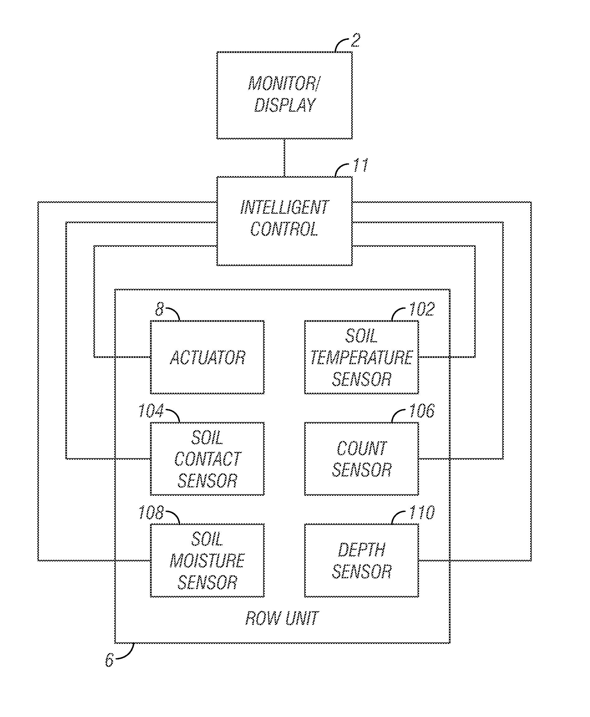
[0053]FIG. 3 illustrates one example of a system which includes a planter 4 having a control system 5. The control system 5 may include an intelligent control 11 operatively connected to a monitor 2. There may be a plurality of row units 6. For each row unit 6, there is an actuator 8 and sensors 7, 9. The sensors 7, 9 may include a soil moisture sensor, a seed to soil contact sensor, soil temperature sensor and seed trench depth sensor for adjusting seed planting depth and row unit down pressure on-the-go while planting.

[0054]FIG. 4 illustrates another example of the invention. As shown in FIG. 4, an intelligent control 11 is operatively connected to a monitor or display 2. The intelligent control unit 11 is also operatively connected...


PUM


Abstract

An on-the-go monitor and control means and method for an agriculture machines includes on-the-go soil sensors that can be used to control tillage and seeding depth. On seeder implements, the sensors provide information that affects uniform plant emergence.

Description

FIELD OF THE INVENTION[0001]The present invention relates generally to agricultural machines, and more specifically, to on-the-go sensors that measure soil parameters affecting optimum planting and tillage depth. An electronic control system may automatically adjust planting or tillage depth on-the-go based on measured soil parameters.BACKGROUND OF THE INVENTION[0002]In crops like corn, uniform seed germination and plant emergence are critical to achieve maximum yield potential. According to The Ohio State University Extension Fact Sheet Tips to Reduce Planter Performance Effects on Corn Yield, “Uneven emergence affects crop performance because competition from larger early-emerging plants decreases the yield from smaller later-emerging plants.”“Emergence delays of 10 days or more usually translate to growth stage differences of two leaves or greater. Therefore, if two plants differ by two leaves or more, the younger, smaller plant is more likely to be barren or produce nubbins.” It...

Claims


Application Information

Patent Timeline
IPC IPC(8): A01C7/10G01B5/18G01K1/02A01C21/00G01N19/10
CPCA01C7/10A01C21/00G01B5/18G01K1/02G01N19/10G01B21/18G01K1/14G01N33/24Y10S111/903A01C7/203A01C5/068A01C7/20A01C7/105A01B63/1115A01B49/06A01B63/008A01B27/00A01C5/062G01B7/26G01B11/22G01N21/27G01N27/223
Inventor ZIELKE, ROGER R.
Owner LEADER TECH
Learn More