Air moving appliance with on-board diagnostics

a technology of air moving appliances and diagnostics, applied in the direction of single motor speed/torque control, synchronous motor starters, heating types, etc., can solve the problems of affecting the performance of the motor, affecting the accuracy of the system, and affecting the efficiency of the airflow system, so as to reduce the computational overhead and enhance the system's accuracy.

Active Publication Date: 2014-10-23
DYSON TECH LTD
View PDF64 Cites 44 Cited by
  • Summary
  • Abstract
  • Description
  • Claims
  • Application Information

AI Technical Summary

Benefits of technology

[0009]The invention provides an advantage that the process of monitoring a parameter that is indicative of the load on the motor is unaffected by the ambient environmental conditions of the appliance. So, the monitored motor load parameters are, in effect, corrected for the influence of ambient air density on the motor in order to diagnose fault conditions within the air flow system of the appliance accurately and reliably.
[0012]The compensating means may calculate the compensated reference motor load parameter at repeated intervals during the operation of the appliance. However, in order to reduce computational overhead, it is envisaged that it is sufficient for the compensating means may only to carry out its calculation when the appliance is turned on.
[0016]In addition to monitoring for a fault condition that reduces the load on the motor by reducing the mass air flow therethrough, the invention may include comparing the motor load parameter value against a second reference motor load parameter value which is indicative of the appliance being activated without an associated filter or separating system installed in the airflow path of the appliance. For example, if a vacuum cleaner is activated without its separating system in place, or without a pre-motor filter in place, this would increase the air mass flow through the appliance thereby imposing an increased load on the motor. The motor would therefore draw more power in a motor system controlled to operate at a substantially constant speed, or would run at a lower speed in a motor system controlled to operate at a substantially constant output power.

Problems solved by technology

Continued operation of the vacuum cleaner when it is in a full state may impair its performance or may cause blockages in other parts of the vacuum cleaner so prompt attention is desirable.
A similar issue can arise with filters which become blocked.
Over-loaded filters present an undesirable resistance to airflow and a resultant loss of airflow power.
However, in practice such a diagnostic method lacks robustness across a range of operating conditions of the vacuum cleaner so its usefulness is limited.

Method used


Image

  • Air moving appliance with on-board diagnostics
  • Air moving appliance with on-board diagnostics
  • Air moving appliance with on-board diagnostics

Examples


Embodiment Construction

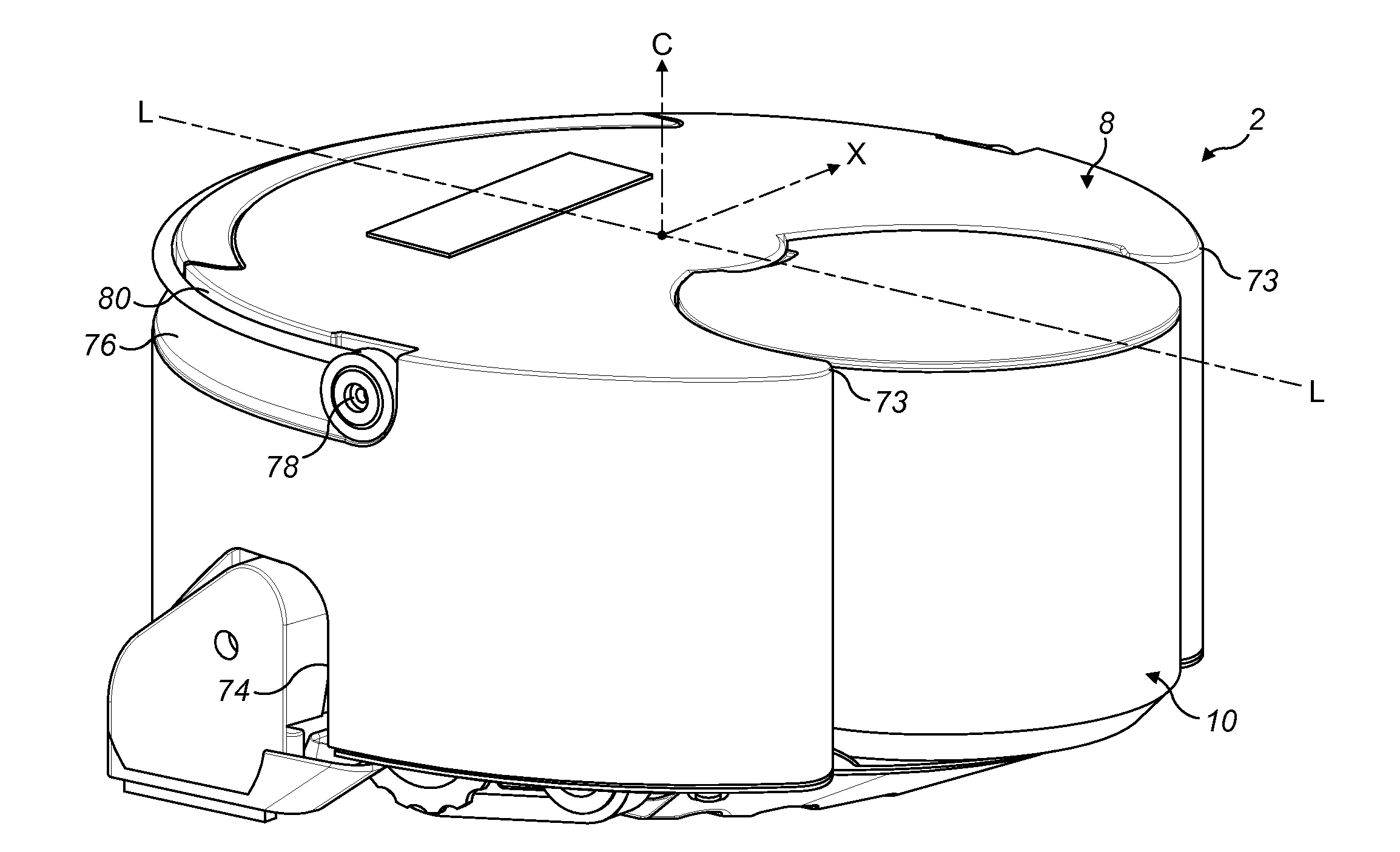
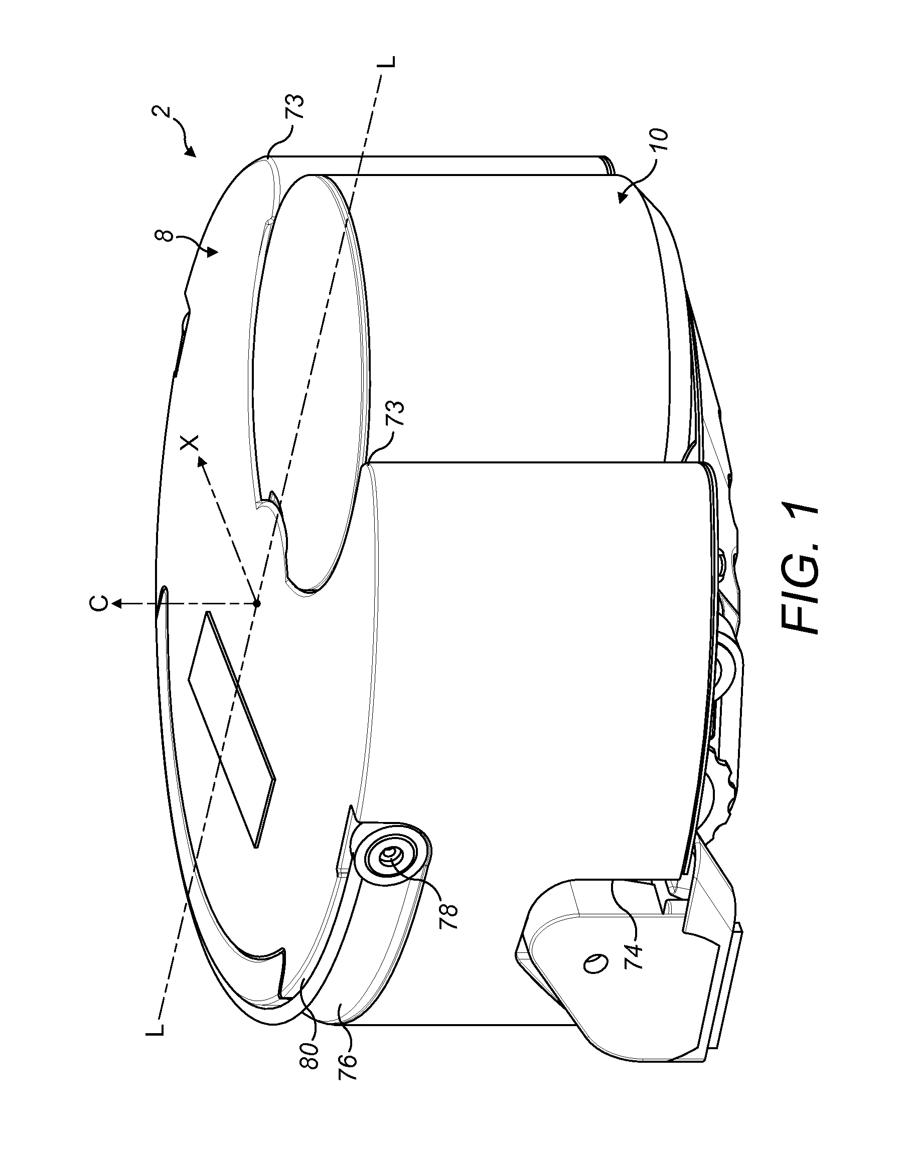
[0029]With reference to FIGS. 1, 2, 3 and 4 of the drawings, an appliance, in the form of a mobile robotic vacuum cleaner 2 (hereinafter ‘robot’) comprises a main body having four principal assemblies: a chassis (or sole plate) 4, a body 6 which is carried on the chassis 4, a generally circular outer cover 8 which is mountable on the chassis 4 and provides the robot 2 with a generally circular profile, and a separating apparatus 10 that is carried on a forward part of the body 6 and which protrudes through a complementary shaped cut-out 12 of the outer cover 8.

[0030]For the purposes of this specification, the terms ‘front’ and ‘rear’ in the context of the robot will be used in the sense of its forward and reverse directions during operation, with the separating apparatus 10 being positioned at the front of the robot. Similarly, the terms ‘left’ and ‘right’ will be used with reference to the direction of forward movement of the robot.

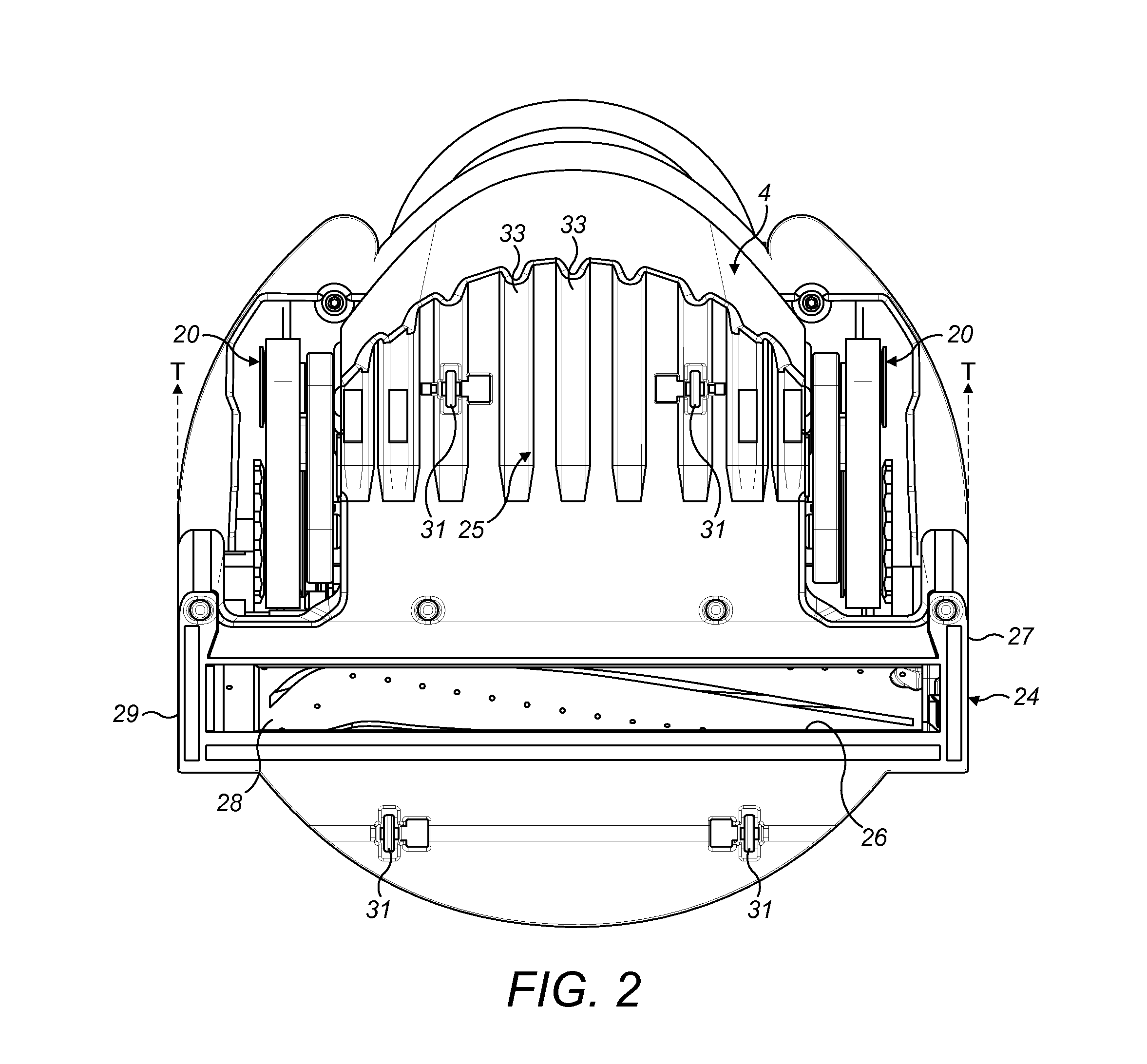
[0031]The chassis 4 supports several components of...


PUM


Abstract

An air moving appliance comprising an electric motor coupled to a fan, a control system for controlling the motor, the control system including monitoring means configured to monitor a motor load parameter; memory means configured to store a predetermined reference motor load parameter value; compensating means that determines a compensated reference motor load parameter value based on the predetermined reference motor load parameter value and a set of ambient environment input conditions; comparison means configured to compare the motor load parameter and the compensated reference motor load parameter value and trigger an operational event based on the result of the comparison. The invention also relates to a method of controlling an air moving appliance.

Description

REFERENCE TO RELATED APPLICATIONS[0001]This application claims the priority of United Kingdom Patent Application No. 1307142.8, filed Apr. 19, 2013, the entire contents of which are incorporated herein by reference.FIELD OF THE INVENTION[0002]The invention relates to an air moving appliance and in particular, although not exclusively to a vacuum cleaner. More specifically, the invention relates to a method and apparatus to diagnose fault conditions within the airflow passages of the air moving appliance.BACKGROUND OF THE INVENTION[0003]As is well known, vacuum cleaners use an electric motor driven fan unit to generate suction which draws dirt-laden air through a dirty air inlet into the body of the vacuum cleaner. The dirty air passes through a separating apparatus, either in the form of a bag or a cyclonic separation system, in order to separate the dirt particles from the air flow.[0004]Whether the separation apparatus involves a bagged or a ‘bagless’ system, the vacuum cleaner mu...

Claims


Application Information

Patent Timeline
Patent Type & Authority Applications(United States)
IPC IPC(8): A47L9/28H02P6/00
CPCA47L9/2831A47L9/2852A47L9/2842H02P6/001A47L9/12A47L9/2821A47L2201/06H02P6/34F24F2110/00F24F11/30F24F6/00H02H7/0833
Inventor MURCHIE, RUSSELL SCOTTVANDERSTEGEN-DRAKE, MARK STAMFORD
Owner DYSON TECH LTD
Why Eureka
Try Eureka