Rechargeable Lithium Ion Button Cell Battery

Active Publication Date: 2014-10-23
ZHUHAI ZHI LI BATTERY
View PDF8 Cites 19 Cited by
  • Summary
  • Abstract
  • Description
  • Claims
  • Application Information

AI Technical Summary

Benefits of technology

[0018]The other option is to weld the cathode tab to an aluminum round flake, and said flake be pressed by said battery gasket upon the outer casing bottom to have reliable contact with the outer casing. This option uses quite small tab to be welded easily on the aluminum flake. Further insulation washer or washers could be applied on the welded aluminum flake surface to prevent any metal from exposing to the electrolyte, to reduce the risk of battery short and also have longer cycle life. One washer is difficult to have the metal flake fully covered and we found by two washers it is much better and easier.
[0019]The third option is to weld the cathode tab directly to the

Problems solved by technology

However, as the tab connecting to the outer casing is in a complicated way, so to fully cover the metal flake by one washer is difficult.
Exposing to the electrolyte of the naked

Method used


Image

  • Rechargeable Lithium Ion Button Cell Battery
  • Rechargeable Lithium Ion Button Cell Battery
  • Rechargeable Lithium Ion Button Cell Battery

Examples


example 1

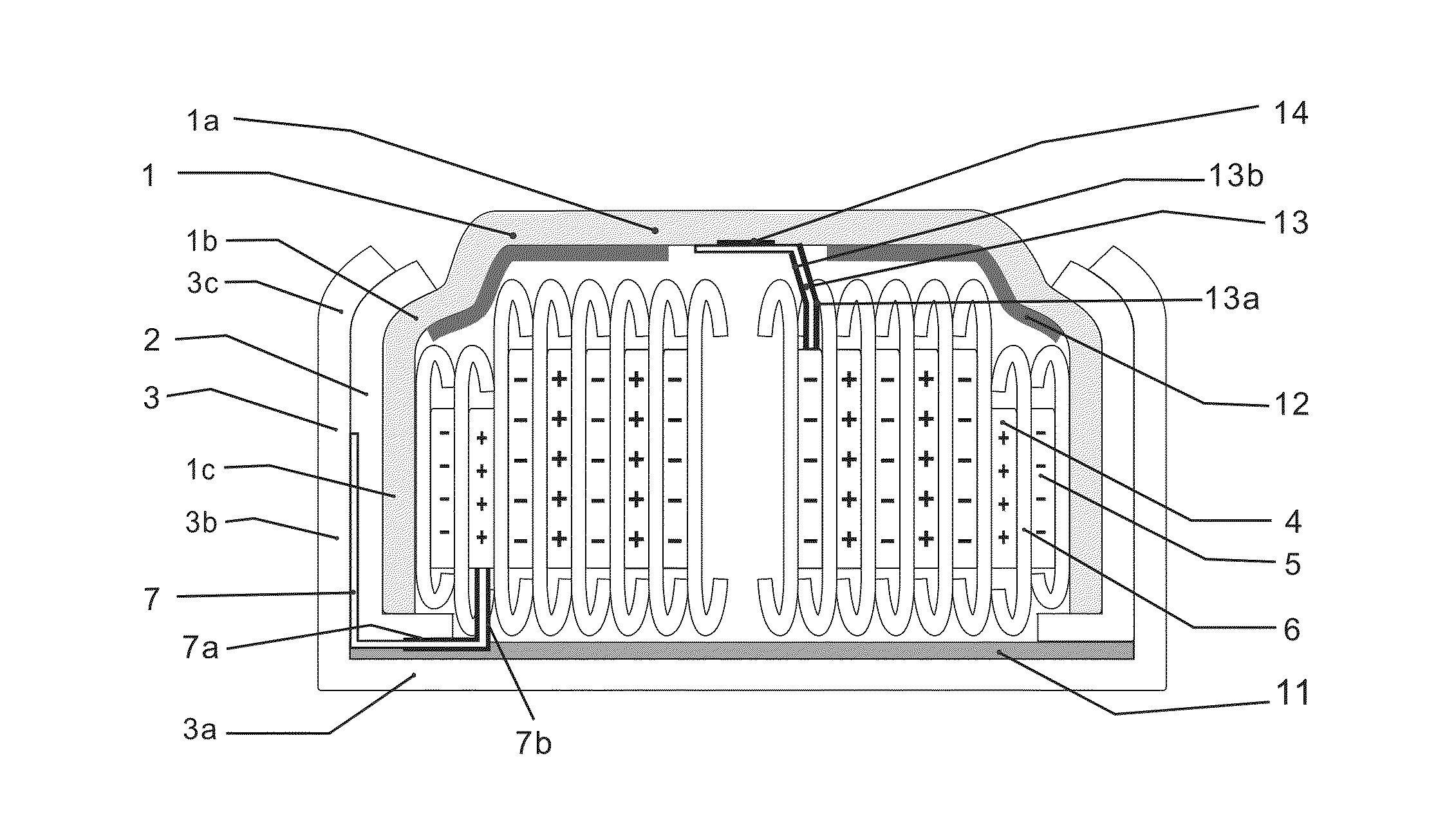
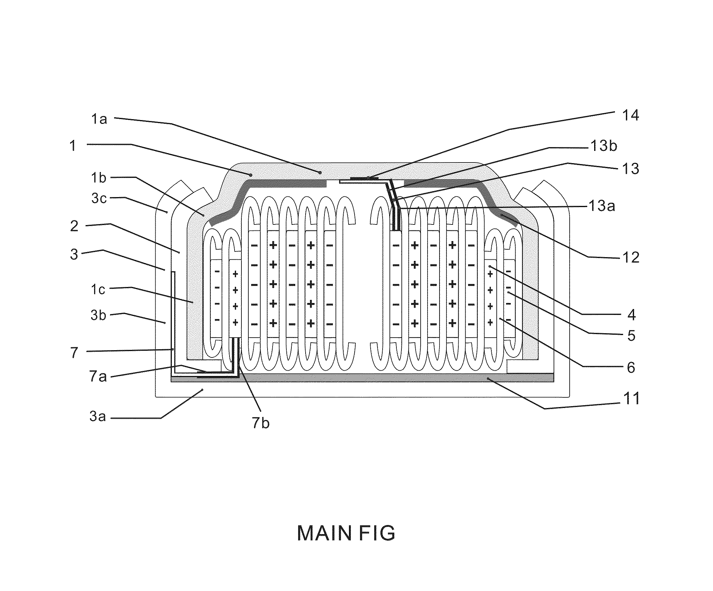
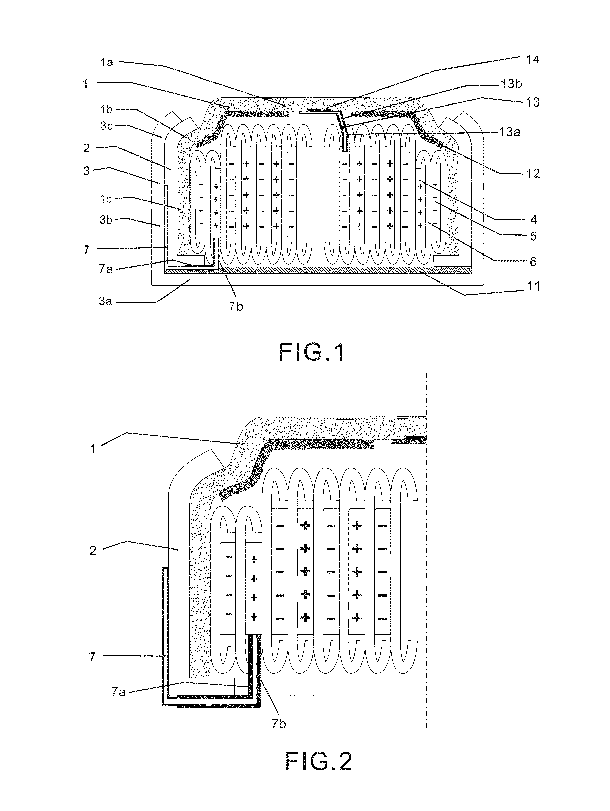
[0046]As per FIG. 1, inventors of the present invention manufactured some lithium-ion rechargeable button cells size Z23 at diameter 7.8 mm height 5.3 mm as per the details disclosed in the above description.

[0047]Battery casings 1 and 3 are made by nickel plated stainless steel grade 316, 304 or 430, of 0.10 mm to 0.15 mm thick, preferably at 0.125 mm thick. The anode casing sidewall 1c is single wall. Gasket 2 is made by injected polypropylene at 0.06 mm to 0.15 mm thick, preferably at 0.12 mm thick.

[0048]Vacuum mix the cathode lithium-intercalating materials preferably Li(Ni1 / 3Mn1 / 3Co1 / 3)O2 and other functional additives in NMP solvent thoroughly, and coat the slurry double sided on the aluminum foil usually 10 um to 25 um thick preferably 12 um thick, heat to dry the coated material and press it by a calendaring machine to get the desired thickness usually 0.1 mm to 0.2 mm. The coating is not on full area of the aluminum foil leaving a blank area uncoated for the battery tab 7. ...

example 2

[0054]As per FIG. 3, most of the parts, materials and procedures are the same as example 1, except that the cathode tab 7 is welded to a round metal flake 10 usually aluminum flake at 0.05 mm thick, as FIG. 5. Insulation washer 11a is a O ring shape adhesive tape, to be attached to flake 10 before ultrasonic welding, leaving the center metal exposed and then welded with conductor tab 7. After welding insulation washer 11 usually round is attached to the welding area to have all the naked metals covered. After the electrolyte being filled, the flake 10 is then turned down to cover the spiral wound roll and then the outer casing 3 is put onto this sub-assembly then the battery is finally crimped and sealed.

[0055]The battery made in this example has the similar performance as example 1, except that an extra aluminum flake 10 welded to conductor tab 7 and it brings risk of breaking the tab 7 at different assembly steps. It also occupies about 0.05 mm thickness of the battery inside spac...

example 3

[0056]As per FIG. 4, most of the parts, materials and procedures are the same as example 1, except that the cathode tab 7 is much longer and welded directly to the outer casing inner flat area 3a. The longer tab 7 can reach 3a by crossing the sidewall 3b down and then ultrasonic welded with 3a at area 8. Insulation washer 11a is a O ring shape adhesive tape, to be attached to outer casing bottom 3a before ultrasonic welding, leaving the center metal exposed and then welded with conductor tab 7. After welding insulation washer 11 usually round is attached to the welding area to have all the naked metals covered. The long neck of tab 7 will have to hold the outer casing 3 together with the spiral wound roll during all the steps afterward. After the electrolyte being filled, the outer casing 3 is then turned back from aside to cover the sub-assembly while the lengthy tab 7 must be carefully bended for several times to be contained inside of the battery housing, and then the battery is ...


PUM


Abstract

A rechargeable lithium ion button cell battery having a sealed housing comprises an inner casing and an outer casing, both casings have at least one flat area as top or bottom of the battery, and a round or oval sidewall vertically formed to the flat area. An insulation gasket is positioned between said sidewalls, and the outer casing opening is mechanically crimped to complete the seal of the battery. Inside the sealed housing the anode and cathode electrodes are spiral wound with separator to be a round or oval roll. Said roll axis is vertical to the said flat areas of the casings. The two electrodes are tapered in width to fully utilize the inner space. The electrodes comprise current collectors of metal foils coated with lithium-intercalating active materials, leaving small area of uncoated metal foils as conductor tabs for connecting the electrodes to the casings. The tabs could be welded or by tight contacting to the casings, in several options. Insulation washers or tapes are applied to the naked metal surfaces of the electrodes or casings inside of the housing to prevent short circuit and enable the battery to have longer cycle life.

Description

RELATED APPLICATION[0001]This application is a Continuation-in-Part of U.S. patent application Ser. No. 12 / 881,179 filed Sep. 14, 2010, published on Apr. 21, 2011 Pub. No. US 2011 / 0091753A1 cited as reference herein.REFERENCES CITED[0002]US PATENT DOCUMENTS5,427,874May 1994Sugeno429 / 194Non-aqueous liquid electrolyte secondary cell5,582,930May 1995Oltman et al.429 / 27 High energy density metal-air cell5,629,107January 1996Shioda et al.429 / 128Coin-shaped lithium battery6,248,476June 1999Sun et al.429 / 224Metal air cathode and electrochemical cells made therewith6,265,100February 1998Saaski et al.429 / 163Rechargeable battery6,451,472April 2000Chang et al.429 / 94 Lithium battery and manufacturing method thereof6,567,527August 2000Baker et al.381 / 323Elongated oval battery assembly for canal hearing device6,713,215January 2001Watanabe et al.  429 / 231.5Non-aqueous electrolyte rechargeable batteries6,761,995August 2001Uyama et al.429 / 171Coin-shaped battery6,794,082September 2001Mori et al.429 / 1...

Claims


Application Information

Patent Timeline
IPC IPC(8): H01M10/04H01M50/469H01M50/534H01M50/538
CPCH01M10/0431H01M10/0525H01M10/0587H01M50/109H01M50/171H01M50/538H01M50/534H01M50/469Y02E60/10Y02P70/50
Inventor WANG, FANG
Owner ZHUHAI ZHI LI BATTERY
Why Eureka
Try Eureka