Window of aircraft, aircraft, and assembly method for window of aircraft

Active Publication Date: 2014-10-30
MITSUBISHI AIRCRAFT
View PDF14 Cites 3 Cited by
  • Summary
  • Abstract
  • Description
  • Claims
  • Application Information

AI Technical Summary

Benefits of technology

The present invention is about a conductive seal member that can provide waterproof, moisture-proof, and airtightness, as well as electromagnetic shielding. This seal member is easy to install and can be mounted between an outer retainer and a connecting film at a low cost.

Problems solved by technology

1) a greater dependence on electric / electronic systems that execute required functions for continued safe flight and landing and takeoff of aircraft;
2) a decrease in electromagnetic shielding by a certain type of composite material used in design of aircraft;
3) an increase in susceptibility (sensitivity) of electric / electronic systems to HIRF along with increases in operating speed of data buses or processors, density of ICs or cards, and sensitivity of electronics;
4) an expansion of a usage frequency particularly to a high-frequency band of 1 GHz or more;
5) an increase in severity of an HIRF environment along with an increase in the number of RF transmitters and electric power; and
6) an adverse effect on part of aircraft when exposed to HIRF.
Meanwhile, inside aircraft, there may be an adverse effect on, for example, communications with an airport control tower, and communications or control of navigation for a flight along a predetermined route due to radio waves or electromagnetic noise (simply referred to as electromagnetic noise below) from various electronics such as mobile phones, game machines, and notebook computers, or PEDs (Personal Electro Devices) such as active-type RFID (Radio Frequency IDentification) tags attached to air cargos.

Method used


Image

  • Window of aircraft, aircraft, and assembly method for window of aircraft
  • Window of aircraft, aircraft, and assembly method for window of aircraft
  • Window of aircraft, aircraft, and assembly method for window of aircraft

Examples


Embodiment Construction

[0030]In the following, the present invention is described in detail based on an embodiment shown in the accompanying drawings.

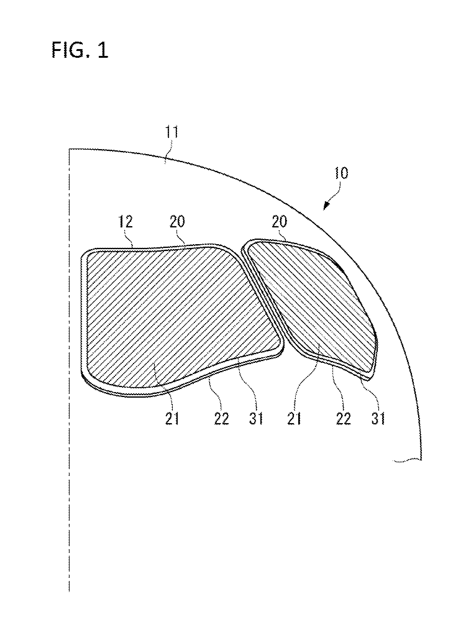
[0031]FIG. 1 is a view for explaining a configuration of a window 20 of an aircraft 10 in the present embodiment.

[0032]As shown in FIG. 1, the window 20 is provided at the front of a cockpit of the aircraft 10.

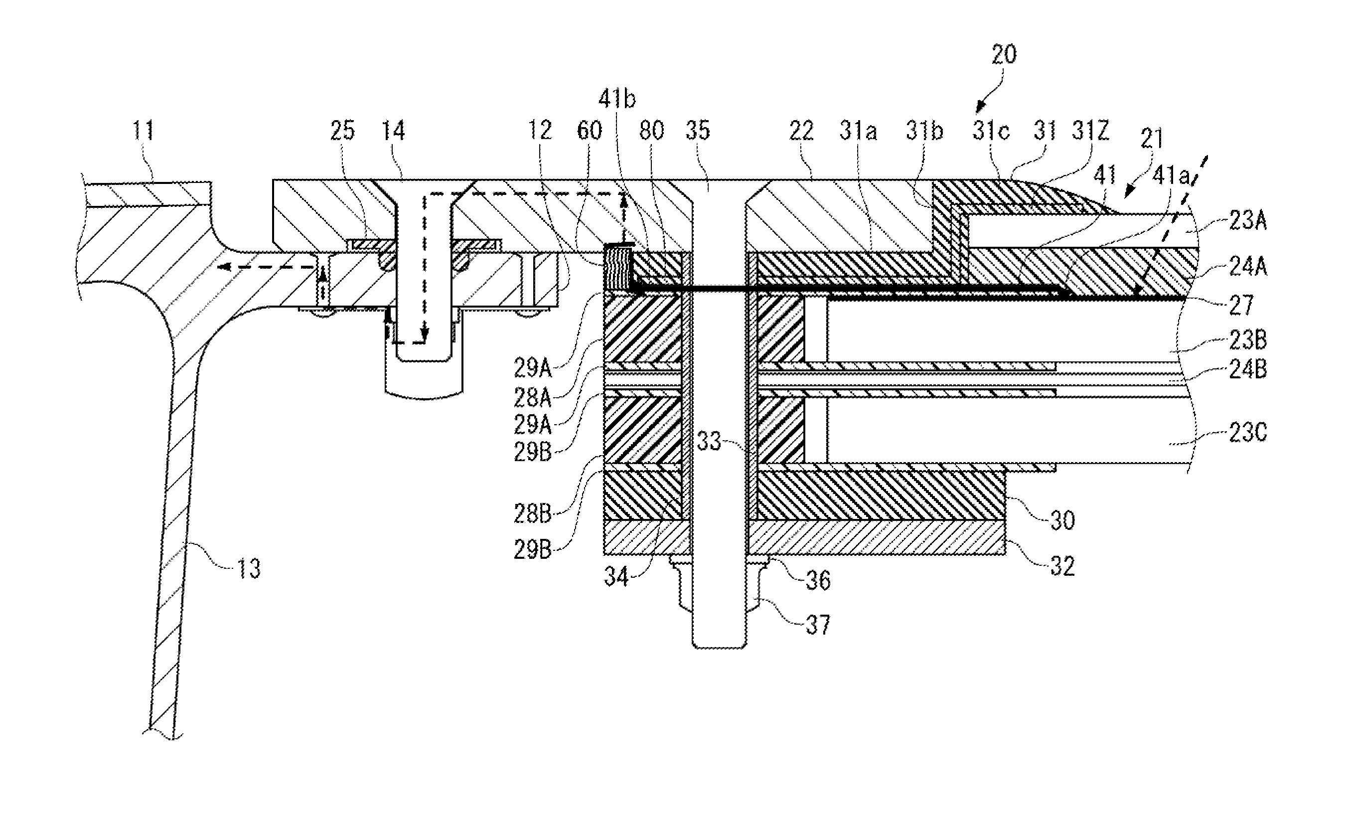
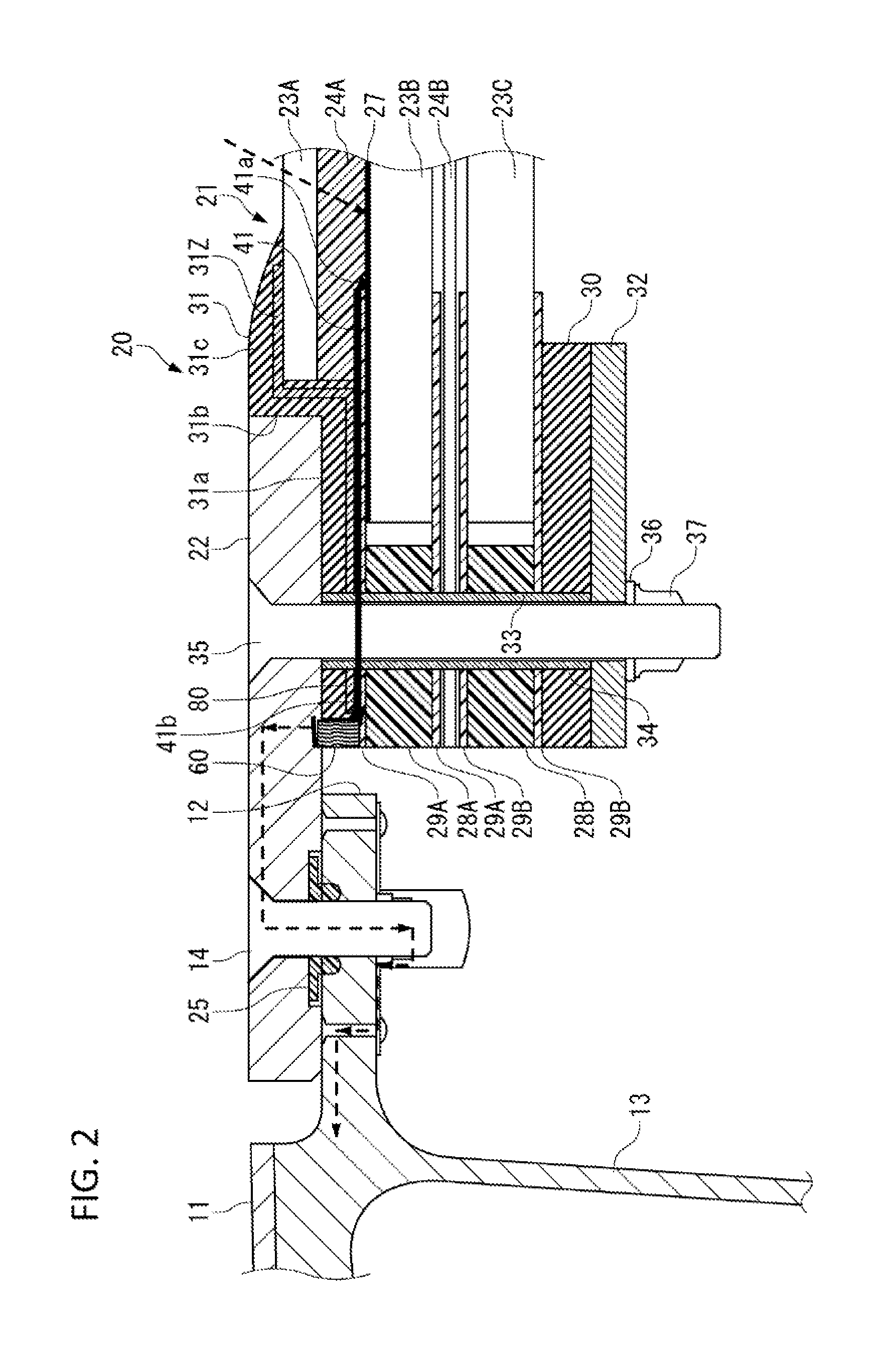
[0033]As shown in FIG. 2, the window 20 is mounted to a window frame 12 that is formed on an outer skin 11 constituting an airframe of the aircraft 10. The window 20 includes a window section 21, and an outer retainer 22 that surrounds an entire outer peripheral portion of the window section 21.

[0034]The window section 21 includes a plurality of, (three in the present embodiment) laminated window panels 23A to 23C. In the window 20 as a main window, at least the window panel 23A, which is an outermost layer facing the outside of the airframe of the aircraft 10, out of the window panels 23A to 23C is made of glass. In the present embodiment, all of the ...


PUM

PropertyMeasurementUnit
Thicknessaaaaaaaaaa
Electrical resistanceaaaaaaaaaa
Electrical conductoraaaaaaaaaa

Abstract

To easily and inexpensively provide a window of an aircraft having sufficient electromagnetic shielding performance and environment-resistant sealing performance, an aircraft, and an assembly method for a window of an aircraft. A conductive seal member 60 is sandwiched between a conductive film 41 and an outer retainer 22. In the conductive seal member 60, thin wire-like materials 62 made of a conductive material such as aluminum are embedded in a seal member body 61 made of a material, such as silicone rubber, having an electric insulating property, waterproofness and pliability. An electromagnetic shielding effect, and environment-resistant sealing properties such as an electric insulating property and waterproofness can be both ensured by the conductive seal member 60.

Description

TECHNICAL FIELD[0001]The present invention relates to a window of an aircraft with an electromagnetic shield, an aircraft, or the like.BACKGROUND ART[0002]Aircraft must be able to fly safely with no malfunction or upset caused during a cruising flight or during landing and takeoff under high intensity radiated fields (HIRF) as an electromagnetic environment from radios, televisions, radars, emitters and other sources. Therefore, HIRF protection measures required in (14CFR) SS23.1308, 25.1317, 27.1317, and 29.1317, High-intensity Radiated Fields (HIRF) protection, which stipulates Regulations (airworthiness requirements) of FAA (Federal Aviation Administration) need to be taken.[0003]Recently, the importance of protection of electric / electronic systems of aircraft has been significantly increasing because of the following reasons:1) a greater dependence on electric / electronic systems that execute required functions for continued safe flight and landing and takeoff of aircraft;2) a de...

Claims


Application Information

Patent Timeline
IPC IPC(8): B64C1/14
CPCB64C1/1484H05K9/0005B64C1/1492Y10T156/10
Inventor YOKOI, TAKASHI
Owner MITSUBISHI AIRCRAFT
Why Eureka
Try Eureka