
Eureka
For R&D, Eureka makes reading and utilizing patents & technical documents easy.
Eureka AIR
Designed for self-driven R&D workflows. Generate viable solutions, solve complex R&D challenges, empower your innovation with AI.

Eureka Materials
Designed for material experts only. Revolutionize your material R&D, from search, analyze, to developing new materials.

TechResearch
Generate reliable direction feasibility study reports for your R&D in just a few steps.

TechSeek
Discover and master advanced knowledge NOW. Basics, ideas, possibilities, all at once.

TechMind
As an expert in R&D Theories, TechMind can generates customized viable solutions instantly.

TechRisk
Analyze your overall solution with one click, know your potential R&D risks in advance.

TechMonitor
Get weekly tech updates, stay abreast of the latest tech innovations and key insights.
Short arc discharge lamp
- Summary
- Abstract
- Description
- Claims
- Application Information
AI Technical Summary
Benefits of technology
Problems solved by technology
Method used
Image

Examples
first embodiment
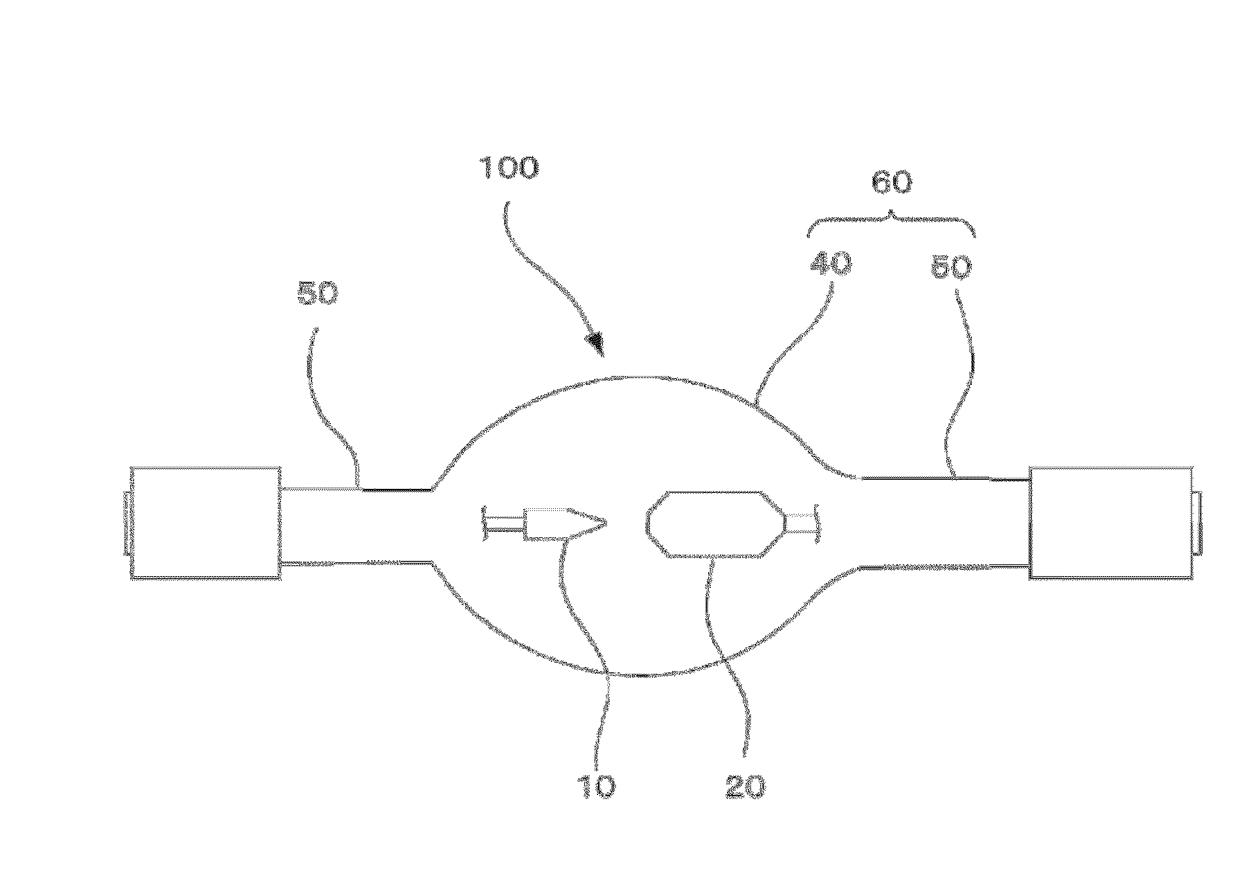
[0039]Preferred embodiments of the present invention will now be described with reference to the drawings. FIG. 1 illustrates a short arc discharge lamp. The short arc discharge lamp of this embodiment is primarily characterized by a configuration (structure) of a cathode, and other components of the discharge lamp are similar to or the same as those of a common short arc discharge lamp. Accordingly, ordinary components of the short arc discharge lamp will be described with reference to FIG. 1. In the following description, it should be noted that the terms “fore,”“front,”“back,”“rear,”“top,”“bottom,”“side” and the like are used for easier understanding of the illustrated structure of the cathode and the discharge lamp, but these terms are only used for easier understanding and have no intention to limit the scope of the invention.
[0040]The discharge lamp 100 has an arc tube 60 that has a light emitting part 40 and sealing parts 50 and 50 at opposite ends of the light emitting part ...
second embodiment
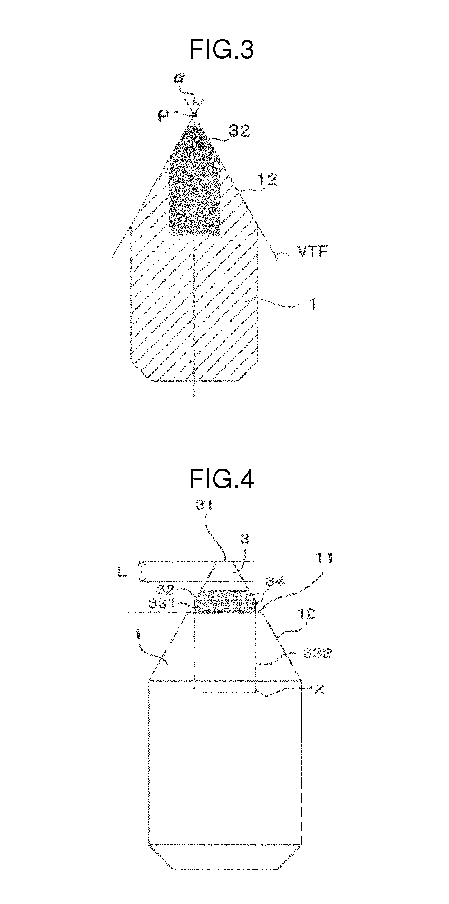
[0067]FIG. 4 illustrates a cathode according to a second embodiment of the present invention. The second embodiment is different from the first embodiment in that a tungsten carbide portion (will be described) is provided in the second embodiment. Therefore, the tungsten carbide will be only described in the second embodiment. Other configurations of the cathode of the second embodiment will be not be described because the description of such configuration is already made in the first embodiment. The same reference numerals and symbols are used in the first and second embodiments to designate the same or similar components in the first and second embodiments.
[0068]In FIG. 4, a rear area of the exposed surface of the electron emitting section 3 is provided with a tungsten carbide portion 34. The tungsten carbide portion 34 extends forward from the position of the annular flat surface portion 11. Specifically, the surface of the cylindrical lateral surface portion 331 of the electron ...
third embodiment
[0099]FIG. 8 illustrates a cathode according to a third embodiment of the present invention. The third embodiment is different from the first embodiment in that there is an annular gap (space) 7 between the rear end of the electron emitting section 3 and the electrode body section 1. In the following description, the same reference numerals are used to designate the same or similar elements in the first and third embodiments and such elements will not be described.
[0100]As shown in FIG. 8, the recess 2 is formed in the front portion of the electrode body section 1, and the electron emitting section 3 is received in the recess 2. The recess 2 has a cylindrical shape, and possesses a bottom. The front portion of the electron emitting section 3 protrudes from the recess 2, and the rear portion of the electron emitting section 3 is firmly received in the recess 2. The rear end face of the electron emitting section 3 generally abuts on the bottom of the recess 2, with the annular gap 7 b...
PUM
 Abstract
Description
Claims
Application Information
 - R&D Engineer
- R&D Manager
- IP Professional
- Industry Leading Data Capabilities
- Powerful AI technology
- Patent DNA Extraction
Browse by: Latest US Patents, China's latest patents, Technical Efficacy Thesaurus, Application Domain, Technology Topic, Popular Technical Reports.
© 2024 PatSnap. All rights reserved.Legal|Privacy policy|Modern Slavery Act Transparency Statement|Sitemap|About US| Contact US: help@patsnap.com