Phase locked loop with simultaneous locking to low and high frequency clocks

a phase lock and high-frequency clock technology, applied in the direction of pulse automatic control, electric devices, etc., can solve the problems of low bandwidth, unacceptably long time to align with the phase of the low-frequency clock, high implementation cost,

Active Publication Date: 2014-10-30
MICROSEMI SEMICON
View PDF12 Cites 42 Cited by
  • Summary
  • Abstract
  • Description
  • Claims
  • Application Information

AI Technical Summary

Benefits of technology

[0013]Embodiments of the invention address the issues with prior art by using a novel approach of independently sampling high-frequency clock and low-frequency sync, and subtracting the detected sync position from the average edge position of the high-frequency clock. This approach allows for ve...

Problems solved by technology

Such a low bandwidth implies an unacceptably long time to align with the phase of the low-frequency clock.
The disadvantages of this method are complexity and high cost of implementation (due to the requirement of extracting the low-frequency sync phase, and switching between the locking modes), and the lack of a mechanism that can perform automatic phase adjustments when the low-frequency sync is disrupted or changes phase.
Phase jumps at the output of the PLL, when switching between NCO and PLL regular locking mode, are also a common problem with this method.
Although this method is simpler than the hybrid method, it lacks flexibility and ease of application.
It also requires compli...

Method used


Image

  • Phase locked loop with simultaneous locking to low and high frequency clocks
  • Phase locked loop with simultaneous locking to low and high frequency clocks
  • Phase locked loop with simultaneous locking to low and high frequency clocks

Examples


Embodiment Construction

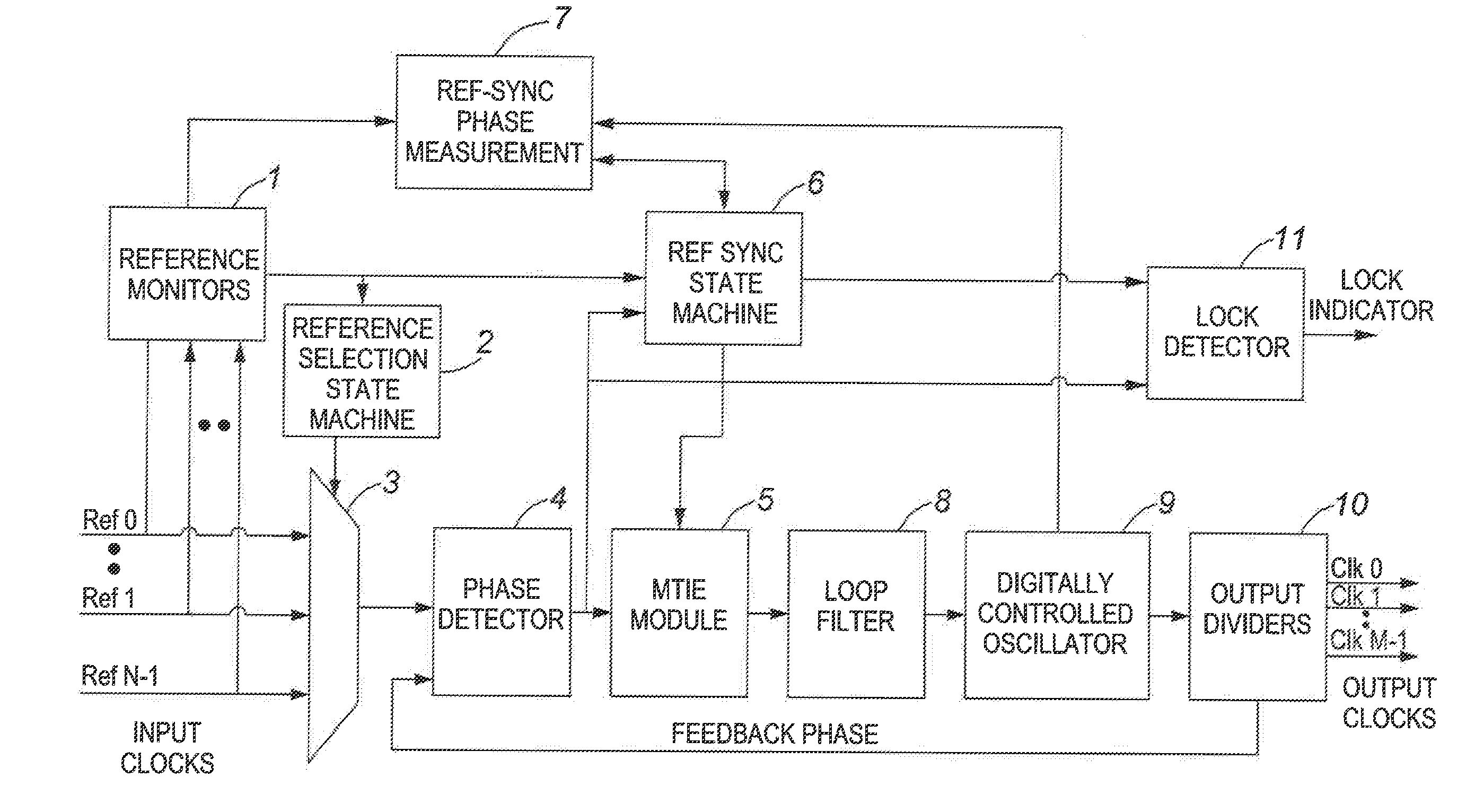
[0030]Reference will now be made to FIG. 5, which shows a high level block diagram of a PLL circuit according to an embodiment of the invention.

[0031]Reference monitor module 1 determines the existence, the short-term and the long-term quality of the input reference clocks, based on specified criteria, and notifies the reference selection state machine module 2 about the clocks' reliability. Hysteresis functionality is implemented in the reference monitor module 1 such that bouncing between references is prevented when the frequency offset of the preferred input reference clock is close to the reliability boundary.

[0032]The reference selection state machine module 2 controls the input reference multiplexer 3, which selects appropriate reference inputs. The reference inputs may be high or low frequency, but preferably there should be at least one high-frequency reference and at least one low-frequency reference available at the input to reference multiplexer 3. The multiplexer 3 can ...


PUM


Abstract

A phase-locked loop to is simultaneously synchronized to high and low frequency clocks by (i) locking an output of the phase-locked loop to a high-frequency reference clock, (ii) measuring at a high rate a first phase difference between the high-frequency reference clock and the output of the phase-locked loop, (iii) measuring at a high rate a second phase difference between a low-frequency reference clock and the output of the phase-locked loop; (iv) computing at a low rate from said first and second phase differences a third phase difference between the high-frequency and low frequency clocks; (v) combining at a low rate said third phase difference with said second phase-difference to obtain a total phase difference; and (vi) adjusting the output of the phase-locked loop at a low rate to reduce the obtained total phase difference.

Description

CROSS REFERENCE TO RELATED APPLICATION[0001]This application claims the benefit under 35 USC 119(e) of U.S. provisional application No. 61 / 816,906 filed Apr. 29, 2013.FIELD OF THE INVENTION[0002]This invention belongs to the field of clock synchronization, and in particular to a method of synchronizing a phase-locked loop (PLL) to both low-frequency and high-frequency reference clocks at the same time.BACKGROUND OF THE INVENTION[0003]Over the years it has become standard practice to use a stable and accurate low-frequency clock or frame pulse (also referred to as a low-frequency sync) to periodically adjust the phase of synchronized devices and equipment locked to a high frequency reference. The high-frequency reference clock could be, for example, a T1 reference (1.544 MHz) up to say 156.25 MHz, whereas the low frequency clock could be from say 1 Hz, for example, in the case of a GPS signal, to an 8 KHz framing pulse.[0004]In order to use such a clock as a reference for a PLL, and ...

Claims


Application Information

Patent Timeline
IPC IPC(8): H03L7/10
CPCH03L7/10H03L7/087H03L7/095H03L7/101
Inventor MITRIC, KRSTESCHRAM, PAULZARGAR, TANMAYCOLBY, DAVIDZHANG, CATHYVAN DER VALK, ROBERTUS
Owner MICROSEMI SEMICON
Why Eureka
Try Eureka