Method and system for producing a synthesis gas using an oxygen transport membrane based reforming system with secondary reforming and auxiliary heat source

a technology of oxygen transport membrane and synthesis gas, which is applied in the field of method and system for producing synthesis gas in an oxygen transport membrane based reforming system, can solve the problems of excessive carbon formation, complex installation, and high cost of conventional methods of producing synthesis gas such as the abov

Active Publication Date: 2014-10-30
PRAXAIR TECH INC
View PDF5 Cites 37 Cited by
  • Summary
  • Abstract
  • Description
  • Claims
  • Application Information

AI Technical Summary

Problems solved by technology

However, both the ATR and POx processes require separate air separation units (ASU) to produce high-pressure oxygen, which adds complexity as well as capital and operating cost to the overall process.
As can be appreciated, the conventional methods of producing a synthesis gas such as have been discussed above are expensive and require complex installations.
There is an operational problem with all of these oxygen transport membrane based systems because such oxygen transport membranes need to operate at high temperatures of around 900° C. to 1100° C. Where hydrocarbons such as methane and higher order hydrocarbons are subjected to such high temperatures within the oxygen transport membrane, excessive carbon formation occurs, especially at high pressures and low steam to carbon ratios.
The carbon formation problems are particularly severe in the above-identified prior art oxygen transport membrane based systems.
Other problems that arise with the prior art oxygen transport membrane based reforming systems are the cost of the oxygen transport membrane modules and the lower than desired durability, reliability and operating availability of such oxygen transport membrane based reforming systems.
These problems are the primary reasons that oxygen transport membranes based reforming systems have not been successfully commercialized.

Method used


Image

  • Method and system for producing a synthesis gas using an oxygen transport membrane based reforming system with secondary reforming and auxiliary heat source
  • Method and system for producing a synthesis gas using an oxygen transport membrane based reforming system with secondary reforming and auxiliary heat source
  • Method and system for producing a synthesis gas using an oxygen transport membrane based reforming system with secondary reforming and auxiliary heat source

Examples


Embodiment Construction

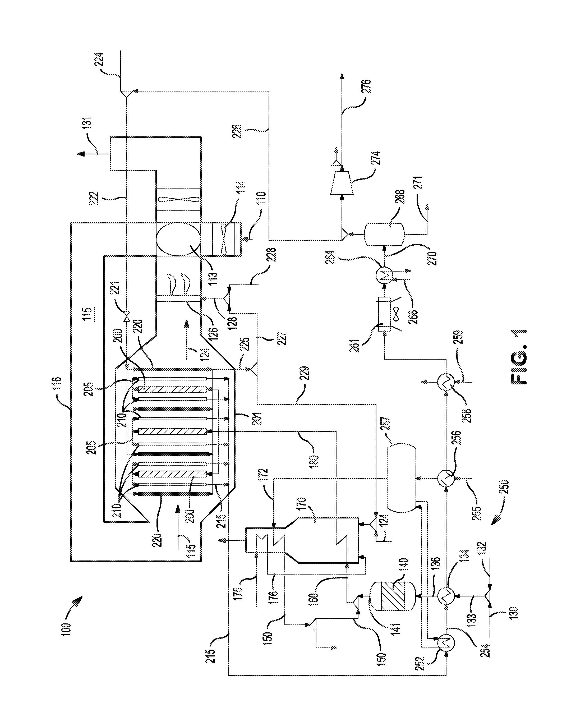
[0023]FIG. 1 provides a schematic illustration of an embodiment of an oxygen transport membrane based reforming system 100 in accordance with the present invention. As seen therein, an oxygen containing stream 110, such as air, is introduced to the system by means of a forced draft (FD) fan 114 into a heat exchanger 113 for purposes of preheating the oxygen containing feed stream 110. Heat exchanger 113 is preferably a high efficiency, cyclic and continuously rotating ceramic regenerator disposed in operative association with the oxygen containing feed stream 110 and a heated oxygen depleted retentate stream 124. The incoming air feed stream 110 is heated in the ceramic regenerator 113 to a temperature in the range of about 850° C. to 1050° C. to produce a heated air feed stream 115.

[0024]The oxygen depleted air leaves the oxygen transport membrane reforming tubes as heated oxygen depleted retentate stream 124 at the same or slightly higher temperature than the heated air feed strea...


PUM

PropertyMeasurementUnit
pressureaaaaaaaaaa
temperaturesaaaaaaaaaa
pressuresaaaaaaaaaa

Abstract

A method and system for producing a synthesis gas in an oxygen transport membrane based reforming system is disclosed that carries out a primary reforming process within a reforming reactor, and a secondary reforming process within an oxygen transport membrane reactor and in the presence of heat generated from a oxygen transport membrane reactor and an auxiliary source of heat. The auxiliary source of heat is disposed within the reactor housing proximate the reforming reactors and may include an auxiliary reactively driven oxygen transport membrane reactor or a ceramic burner.

Description

CROSS REFERENCE TO RELATED APPLICATIONS[0001]This application claims priority to and the benefit of U.S. provisional patent application Ser. Nos. 61 / 816,326 filed on Apr. 26, 2013; 61 / 874,077 filed on Sep. 5, 2013; and 61 / 910,697 filed on Dec. 2, 2013, the disclosures of which are incorporated by reference herein.FIELD OF THE INVENTION[0002]The present invention relates to a method and system for producing a synthesis gas in an oxygen transport membrane based reforming system, and more particularly, a method and system for producing a synthesis gas in an oxygen transport membrane based reforming system that provides both primary and secondary reforming and an auxiliary heat source.BACKGROUND[0003]Synthesis gas containing hydrogen and carbon monoxide is used for a variety of industrial applications, for example, the production of hydrogen, chemicals and synthetic fuel production. Conventionally, the synthesis gas is produced in a fired reformer in which natural gas and steam is refor...

Claims


Application Information

Patent Timeline
Patent Type & Authority Applications(United States)
IPC IPC(8): C07C29/151C07C29/152C01B3/02
CPCC07C29/1518C07C31/04C07C29/152C01B3/02C01B3/382C01B3/384C01B13/0251C01B2203/0233C01B2203/0283C01B2203/043C01B2203/0822C01B2203/0827C01B2203/142C01B3/386Y02P20/10B01J19/245B01J19/2475B01J2219/00121B01J2219/00157B01J2219/24C01B2203/0227C01B2203/0838C01B2203/1235
Inventor CHAKRAVARTI, SHRIKARDRNEVICH, RAYMOND F.STUCKERT, INES C.SHAH, MINISH M.
Owner PRAXAIR TECH INC
Why Eureka
Try Eureka