Solar cell
a solar cell and cell technology, applied in the field of solar cells, can solve the problem that the energy conversation efficiency is approaching the theoretical limit of shockley-queisser, and achieve the effect of improving the photoelectric conversion efficiency and generating photovoltaic power
- Summary
- Abstract
- Description
- Claims
- Application Information
AI Technical Summary
Benefits of technology
Problems solved by technology
Method used
Image
Examples
experiment 1
[Experiment 1]
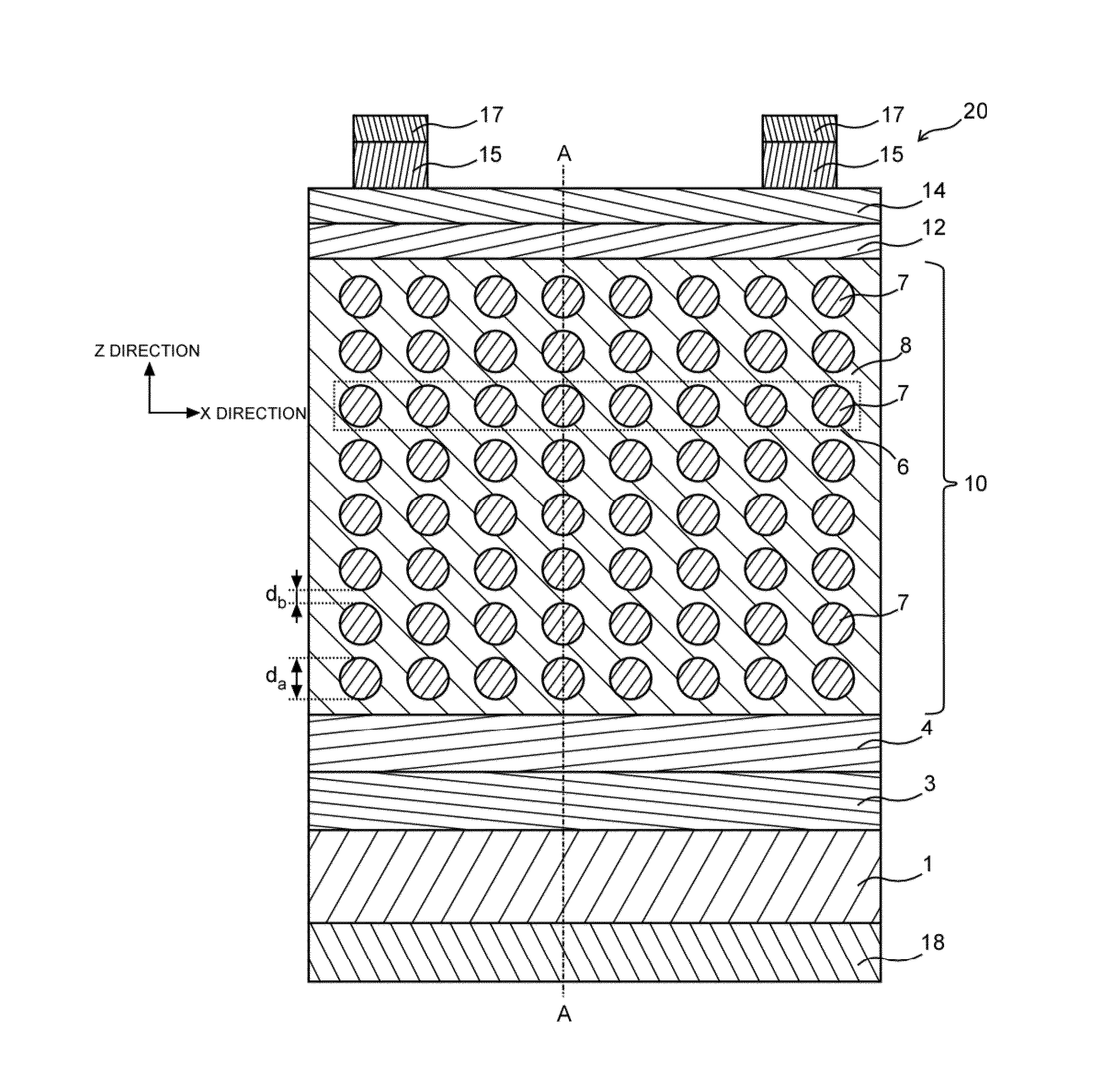
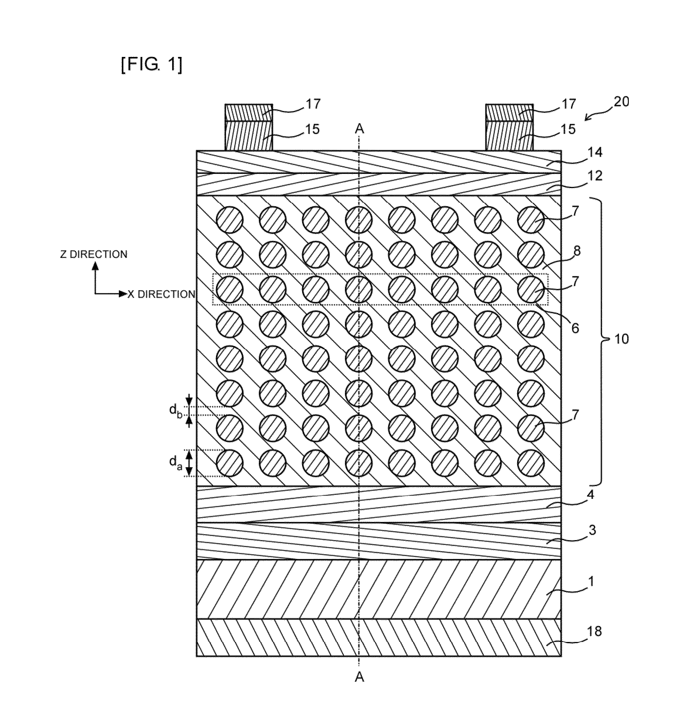
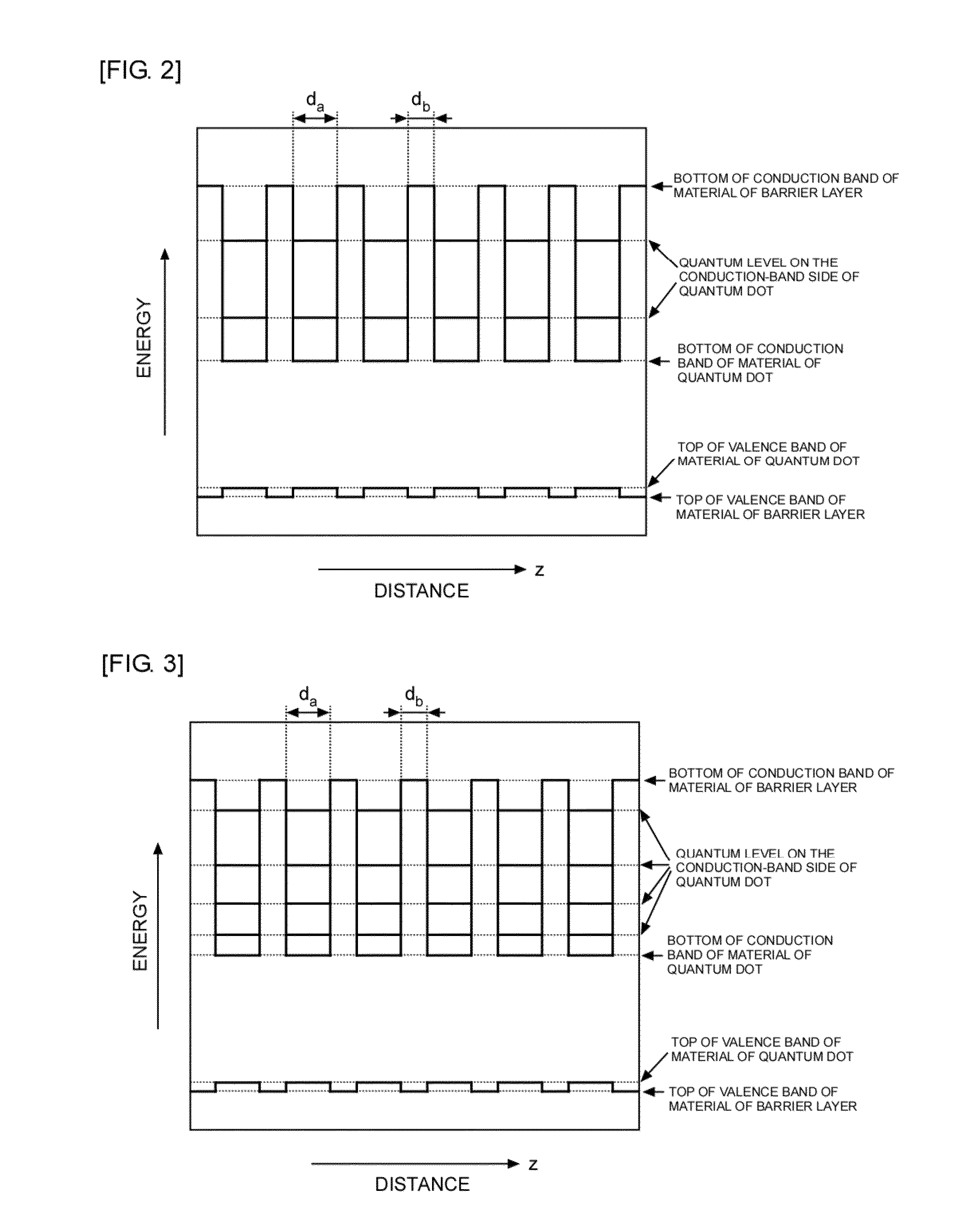
[0176]A simulation experiment was performed on the structure of a 4-level intermediate-band solar cell. As with a technique commonly used for the analysis of semiconductor devices, the simulation was performed by self-consistently solving an equation that indicates that an intermediate band or a localized level is separated from an electrode and that no carrier is taken from the intermediate level to the electrode in addition to Poisson's equation, the electron continuity equation, and the hole continuity equation. The energy conversion efficiencies were calculated and compared, provided that only the dopant concentration was changed and that the remaining conditions were unchanged. In this experiment, the material of the quantum dots was InAs0.7Sb0.3, and the material of the barrier layers was AlSb. The use of these materials enables the band offset of the valence band to be set to substantially zero.
[0177]FIGS. 19 and 20 illustrate the relationship between activated ...
experiment 2
[Experiment 2]
[0182]A simulation experiment was performed on the structure of a 5-level intermediate-band solar cell. The energy conversion efficiencies were calculated and compared, provided that only the dopant concentration was changed. In this experiment, the material of the quantum dots was InAs0.7Sb0.3, and the material of the barrier layers was AlSb.
[0183]FIGS. 23 and 24 illustrate the relationship between activated dopant concentration / density of energy states and energy conversion efficiency / maximum energy conversion efficiency under no concentration conditions. FIGS. 25 and 26 illustrate the results under 1000 suns concentration conditions. FIGS. 23 and 25 are logarithmic graphs. FIGS. 24 and 26 are linear graphs.
[0184]The solar cell is practical when the energy conversion efficiency is at least 80% or more of the maximum energy conversion efficiency (that is, in FIGS. 23 to 26, the value of “energy conversion efficiency / maximum energy conversion efficiency” is 0.8 or more...
experiment 3
[Experiment 3]
[0187]A simulation experiment was performed on the structure of a 6-level intermediate-band solar cell. The energy conversion efficiencies were calculated and compared, provided that only the dopant concentration was changed. In this experiment, the material of the quantum dots was InAs0.7Sb0.3, and the material of the barrier layers was AlSb.
[0188]FIGS. 27 and 28 illustrate the relationship between activated dopant concentration / total density of states and energy conversion efficiency / maximum energy conversion efficiency under no concentration conditions. FIGS. 29 and 30 illustrate the results under 1000 suns concentration conditions. FIGS. 27 and 29 are logarithmic graphs. FIGS. 28 and 30 are linear graphs.
[0189]The solar cell is practical when the energy conversion efficiency is at least 80% or more of the maximum energy conversion efficiency (that is, in FIGS. 27 to 30, the value of “energy conversion efficiency / maximum energy conversion efficiency” is 0.8 or more)...
PUM
 Abstract
Description
Claims
Application Information
 - R&D
- Intellectual Property
- Life Sciences
- Materials
- Tech Scout
- Unparalleled Data Quality
- Higher Quality Content
- 60% Fewer Hallucinations
Browse by: Latest US Patents, China's latest patents, Technical Efficacy Thesaurus, Application Domain, Technology Topic, Popular Technical Reports.
© 2025 PatSnap. All rights reserved.Legal|Privacy policy|Modern Slavery Act Transparency Statement|Sitemap|About US| Contact US: help@patsnap.com


