
Super-Resolution Apparatus and Method

a super-resolution apparatus and super-resolution technology, applied in the field of image-based super-resolution methods, can solve the problems of large amount of calculation and time, low resolution of pet image reconfiguration algorithms, and inability to meet the needs of users, and achieve the effect of quick image reconfiguration process and enhanced resolution

Active Publication Date: 2014-11-06
KOREA ADVANCED INST OF SCI & TECH
View PDF2 Cites 8 Cited by
  • Summary
  • Abstract
  • Description
  • Claims
  • Application Information

AI Technical Summary

Benefits of technology

This patent text describes a new algorithm for reorienting images to improve the resolution of positron emission tomography (PET) scans. The algorithm does not require preprocessing of the image data and uses a special method for parallel processing and a specific format to reduce the complexity of the image reconfiguration process. The technical effect is that it allows for quicker and more efficient image reorienting, resulting in higher-quality PET scans.

Problems solved by technology

A positron emitted from a radioactive isotope consumes all of the self-kinetic energy during a very short period of time after its emission and is coupled with a neighboring electron, thereby becoming extinct.
However, the PET image reconfiguration algorithm has a relatively low resolution and thus, a super-resolution algorithm of generating a plurality of sinogram sets by changing a sampling location through wobbling of a PET system may be applied.
Accordingly, a plurality of reconfiguration processes is performed, leading to using a large amount of calculation and time.
That is, a large amount of calculation and a large amount of time are used, which results in increasing an image reconfiguration complexity.
Thus, when an image reconfiguration is performed based on the sinogram, quality of a PET image may be degraded.
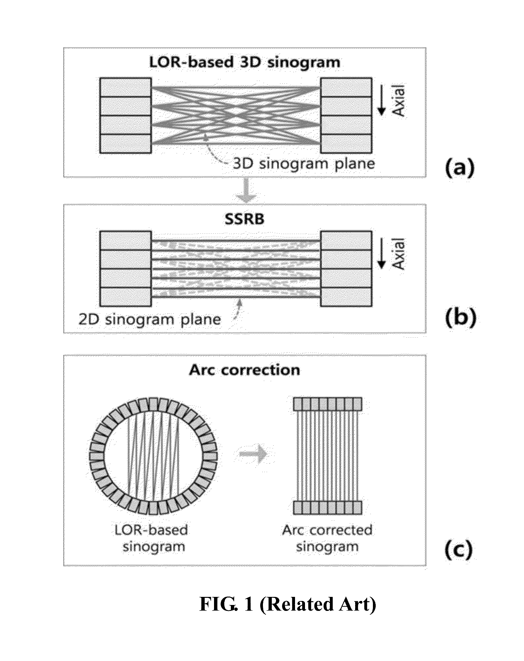
An LOR reconfiguration method according to the related art may be inappropriate for performing such parallel processing operation.
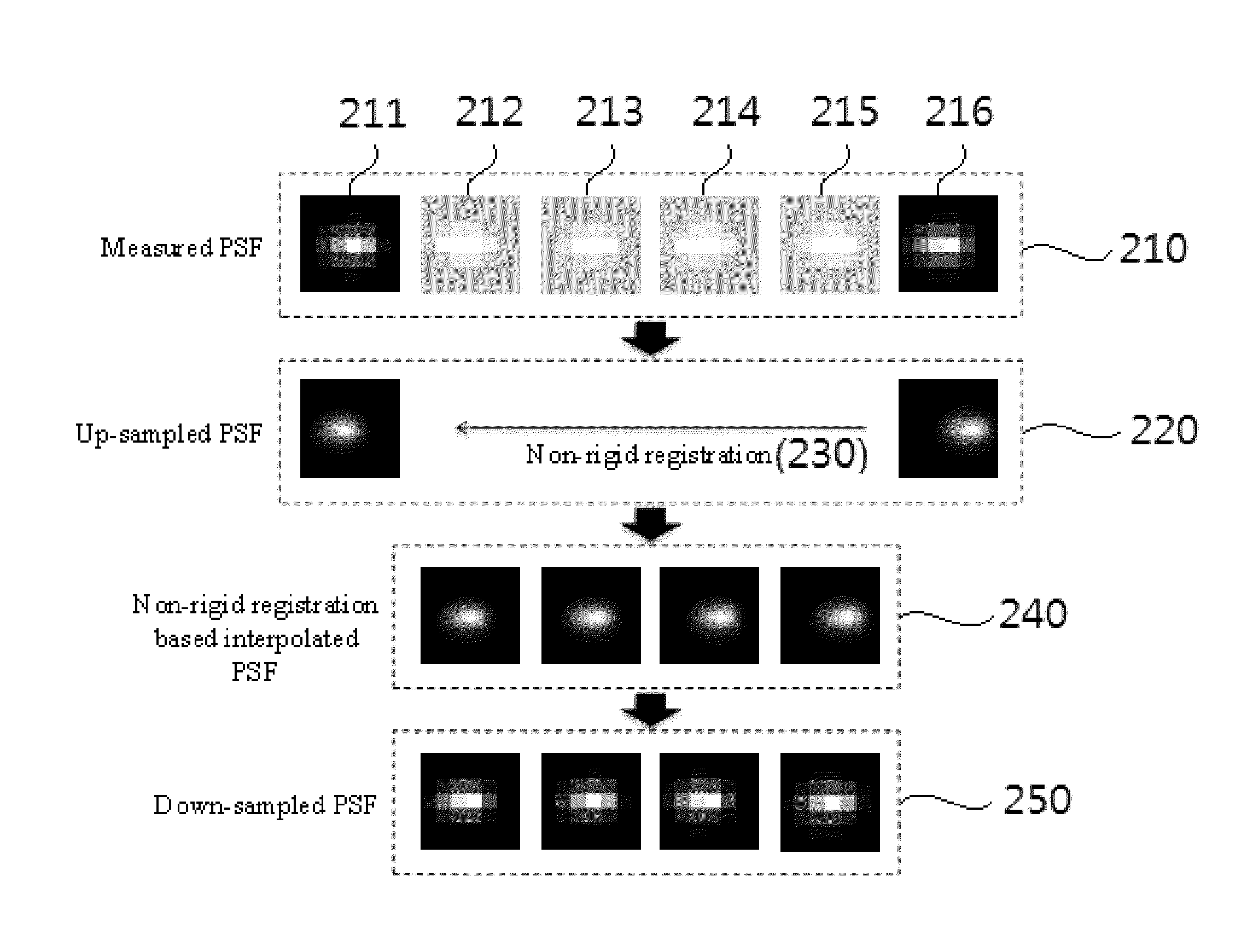
Moreover, it may be substantially impossible for a medical imaging system to measure a point spread function (PSF) with respect to all of voxel locations.
However, when the medical imaging system measures a PSF with respect to all of voxel locations using only the MC simulation, a large amount of calculation may be required.
Accordingly, a large amount of time may be used for processing and a storage memory may also use a large space.

Method used


Image

  • Super-Resolution Apparatus and Method
  • Super-Resolution Apparatus and Method
  • Super-Resolution Apparatus and Method

Examples


Embodiment Construction

[0050]Advantages and features of the present invention and a method to achieve the same will be clearly understood from embodiments to be described by referring to the accompanying drawings. Accordingly, those skilled in the art may easily carryout the technical spirit of the present invention. Also, when it is determined that a detailed description related to a related known function or configuration they may make the purpose of the present invention unnecessarily ambiguous in describing the present invention, the detailed description will be omitted here. Like reference numerals refer to like elements throughout. Hereinafter, embodiments of the present invention will be described with reference to the accompanying drawings.

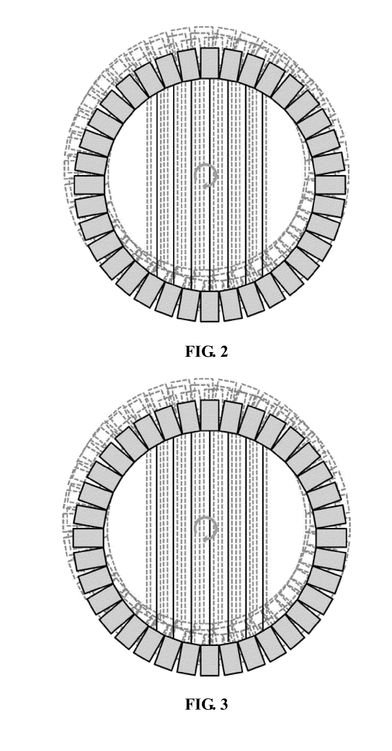
[0051]Initially, point spread function (PSF) kernel-based blur modeling according to the present invention will be described with reference to FIG. 2, and wobbling-based high-resolution sampling will be described with reference to FIG. 3.

[0052]FIG. 2 illustrates...


PUM


Abstract

An image-based super-resolution method using a cone-beam-based line-of-response (LOR) reconfiguration in a positron emission tomography (PET) image is provided. That is, an apparatus and method for reconfiguring a super-resolution PET image using a cone-beam-based LOR reconfiguration is provided.

Description

CROSS-REFERENCE TO RELATED APPLICATION[0001]This application claims the priority benefit of Korean Patent Application No. 10-2013-0049155, filed on May 2, 2013 and Korean Patent Application No. 10-2013-0154555, filed on Dec. 12, 2013 in the Korean Intellectual Property Office, the disclosure of which is incorporated herein by reference.BACKGROUND[0002]1. Field of the Invention[0003]The present invention relates to an image-based super-resolution method using a cone-beam-based line-of-response (LOR) reconfiguration in a positron emission tomography (PET) image, and more particularly, to an apparatus and method for reconfiguring a super-resolution PET image using a cone-beam-based LOR reconfiguration. Further, the present invention relates to a technique for quickly and efficiently acquiring a point spread function (PSF) at each of all voxel locations.[0004]2. Description of the Related Art[0005]A positron emission tomography (PET) has been widely used as one of nuclear medicine test ...

Claims


Application Information

Patent Timeline
IPC IPC(8): G06T11/00
CPCG06T11/005
Inventor RA, JONG BEOMAHN, IL JUNKIM, JI HYECHANG, YONG JIN
Owner KOREA ADVANCED INST OF SCI & TECH
Learn More