Method and apparatus for treating oil containing wastewater

a technology of oil-containing waste water and treatment method, which is applied in biological water/sewage treatment, multi-stage water/sewage treatment, water treatment nature, etc., can solve the problems of insufficient water resources required for production, operation and management, and recycle generated oil-containing waste water, etc., to achieve stable operation, suppress the effect of the second reaction chamber and the following reaction chamber, and easy floatability

Inactive Publication Date: 2014-11-13
SWING
View PDF12 Cites 16 Cited by
  • Summary
  • Abstract
  • Description
  • Claims
  • Application Information

AI Technical Summary

Benefits of technology

[0025]By installing a partition within the biological reaction chamber to have a first reaction chamber, a second reaction chamber, and if necessary, an additional reaction chamber, even when a large amount of oil components or biological inhibiting substances accidentally flows in, the first reaction chamber which receives first the waste water is affected by it and functions as a buffering chamber, and thus the effect on the second reaction chamber and following reaction chambers can be suppressed, yielding a stable operation.
[0026]Further, by forming upflow and downflow flow path within the biological reaction chamber, when the water to be treated is formed to be downflow flow, for example, oil components or activated sludge adsorbed with oil components can be separated as they are readily floatable, and the floating components can be excluded by collecting them using a scum / oil skimmer. Therefore, it is possible that the oil components reaching the membrane separation chamber are reduced to suppress the contamination of the membrane by oil components.
[0027]Further, by collecting the mixture liquid containing activated sludge from the membrane separation chamber, and distributing and returning not only to the first reaction chamber but also to the second reaction chamber, concentration of the activated sludge can be increased in both the second reaction chamber and other reaction chambers at the downflow side, and therefore microorganism decomposition efficiency can be enhanced. Accordingly, even when a large amount of oil components or biological inhibiting substances accidentally flows in and the activated sludge in the first reaction chamber is damaged, the first reaction chamber is affected by it and functions as a buffering chamber, and thus the treatment in the second reaction chamber and other reaction chambers at the downflow side can be stably performed.

Problems solved by technology

In addition, due to an accident occurring in an atomic power plant, presently the energy resource has to rely on petroleum oil, coals, and natural gas.
Meanwhile, among regions in which petroleum oil, coals, and natural gas are obtained in a great amount, many suffer from shortage of water resource, and thus recycling of oil-containing waste water that is generated according to obtainment and production of them is required.
In particular, since there is a tendency that an oil refinery, a petrochemical•coal chemical plant, or the like is located near the region from which energy resources are obtained, water resources required for production, operation, and management are insufficient, and thus nowadays there is no choice but to recycle generated oil-containing waste water.

Method used


Image

  • Method and apparatus for treating oil containing wastewater
  • Method and apparatus for treating oil containing wastewater
  • Method and apparatus for treating oil containing wastewater

Examples


second embodiment

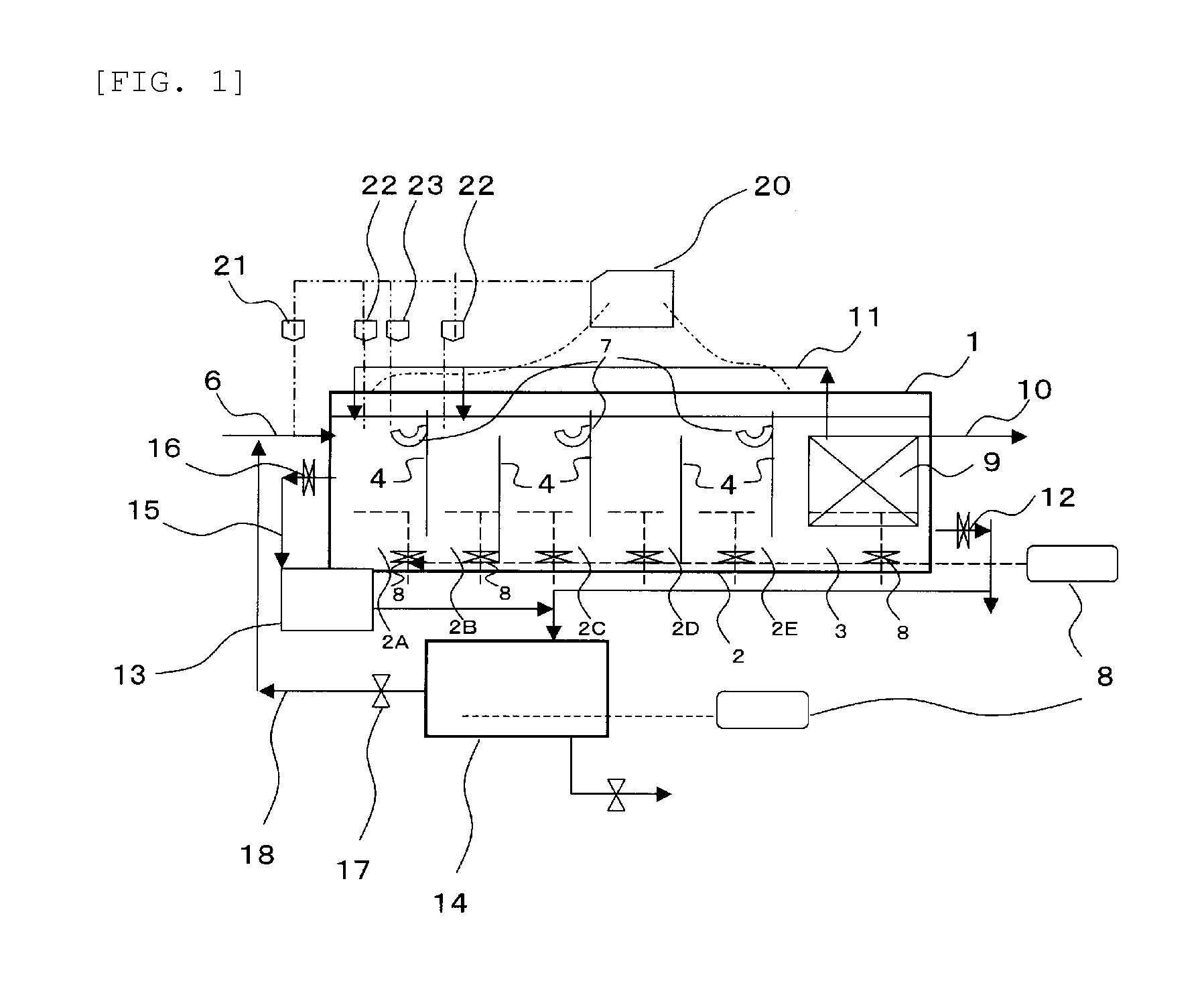
[0143]FIG. 2 is a drawing which illustrates a variation of the waste water treatment apparatus illustrated in FIG. 1, characterized in that an adsorption carrier fixing part 25 is installed within the biological reaction chamber 2.

[0144]The adsorption carrier fixing part 25 is obtained by fixing and disposing a carrier capable of adsorbing hardly decomposing components.

[0145]Examples of the carrier capable of adsorbing hardly decomposing components include activated carbon, various plastic carriers, and sponge carriers. Among them, from the view point of easy adsorption of microorganisms, fibrous activated carbon and particle activated carbon are particularly preferable. Although it is not a carrier which selectively adsorbs hardly decomposing components, it may be any carrier if it can adsorb hardly decomposing components, and it is not limited to the above examples.

[0146]Further, as a means for fixing the carrier, it may be fixed by adding the carrier into a mesh basket. However, ...

third embodiment

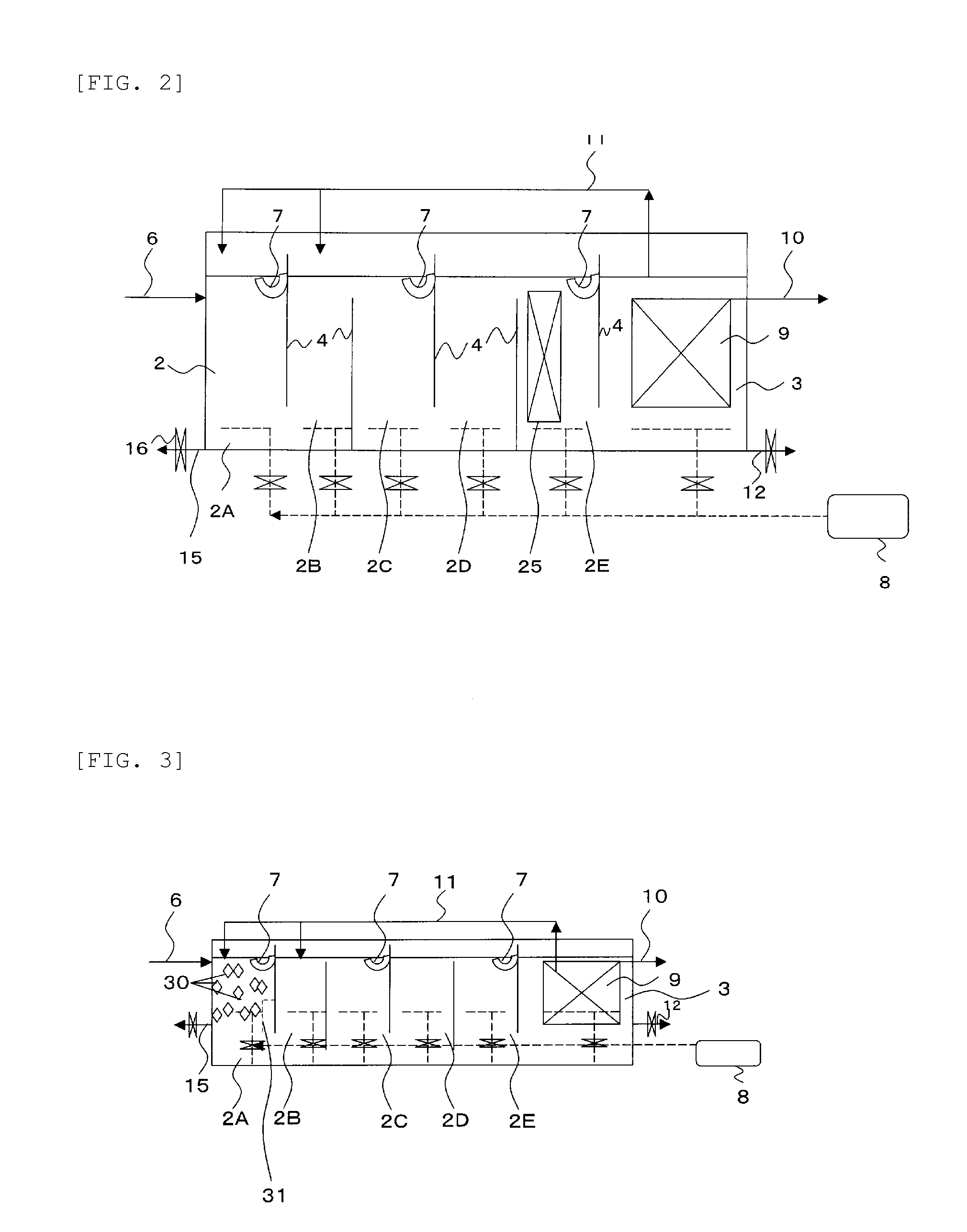
[0150]FIG. 3 is a drawing for illustrating a variation of the waste water treatment apparatus illustrated in FIG. 1, and it is characterized in that a hydrophobic carrier 30 is added and floated in the first reaction chamber 2A and, as illustrated in FIG. 4, a screen 31 is installed at lower connection part between the first reaction chamber 2A and the second reaction chamber 2B.

[0151]Since the oil components flown with the waste water into the first reaction chamber 2A is adsorbed and concentrated by the hydrophobic carrier 30 and also decomposed by neighboring activated sludge, they are generally floating in much lower concentration state than the oil component adsorption capacity of the hydrophobic carrier 30. However, when concentration of the oil components is accidentally increased in the flow-in water, as they are adsorbed onto the hydrophobic carrier 30, the amount of the oil components flown into the second reaction chamber 2B can be suppressed. Once the concentration of th...

fourth embodiment

[0158]FIG. 5(1) and (2) are a drawing for illustrating a variation of the waste water treatment apparatus illustrated in FIG. 1, and it is characterized in that the first reaction chamber 32A and the second reaction chamber 32B that are divided by the partition 4, and also the reaction chambers 32C, 32D, 32E, 32F, and 32G at the downflow side and the separation membrane chamber 33 are not installed in a single row but installed in two rows after folding and overlapping, a distribution chamber 34 is installed between the separation membrane chamber 33 and the first reaction chamber 32A, a gate 35 is installed for connecting the separation membrane chamber 33 to the distribution chamber 34, a gate 36 is installed for connecting the distribution chamber 34 to the first reaction chamber 32A, and a gate 37 is installed for connecting the distribution chamber 34 to the second reaction chamber 32B.

[0159]The waste water flown into the first reaction chamber 32A flows, while moving as a flow...


PUM

PropertyMeasurementUnit
retention timeaaaaaaaaaa
adsorption capacityaaaaaaaaaa
sizeaaaaaaaaaa

Abstract

It relates to a treatment of oil-containing waste water using a membrane biological reactor membrane biological reactor biological reactor (MBR), and it is to provide a new treatment apparatus which is capable of suppressing a reduction in biological treatment activity and suppressing an effect on a separation membrane.Provided is a membrane biological reactor having a biological reaction chamber and a membrane separation chamber, in which the it has a configuration that, within the biological reaction chamber, at least one partition is installed to have a first reaction chamber, a second reaction chamber, and if necessary, an additional reaction chamber so as to form an upflow and downflow flow path, an aeration device and a scum / oil skimmer are installed at least in the first reaction chamber, and a mixture liquid containing activated sludge is withdrawn from the membrane separation chamber and distributed and returned at least to the first reaction chamber and the second reaction chamber.

Description

TECHNICAL FIELD[0001]The present invention relates to a method for treating oil-containing waste water that is generated according to obtainment and production of petroleum oil, coal, natural gas, shale gas, coal bed methane (CBM), oil sand, and shale oil, or oil-containing waste water that is discharged from various plants, for example, oil-containing waste water discharged from a petrochemical plant or an automobile manufacturing plant (taken together, they are referred to as “oil-containing waste water”) and a treating apparatus therefor.BACKGROUND OF THE INVENTION[0002]In recent years, in accordance with significant industrial progresses, population increase, and expansion of metropolitan cities in developing countries, needs for energy resources such as petroleum oil and natural gas increase more than ever before all over the world. In addition, due to an accident occurring in an atomic power plant, presently the energy resource has to rely on petroleum oil, coals, and natural ...

Claims


Application Information

Patent Timeline
Patent Type & Authority Applications(United States)
IPC IPC(8): C02F9/00C02F1/24C02F1/00C02F3/12
CPCC02F9/00C02F3/1268C02F3/1263C02F1/24C02F1/00C02F2101/32C02F2103/365C02F2203/00C02F1/283C02F3/085C02F3/1273C02F3/302C02F2209/10C02F2301/028C02F3/121Y02W10/10
Inventor KITAGAWA, MASAYOSHIMATSUMURA, TAKASHIISOZAKI, HIROKAZUSUZUKI, MASAHIDE
Owner SWING
Why Eureka
Try Eureka