
Method and processing system of sensed ionization current data for real time estimation of combustion chamber pressure in a spark ignition engine

Active Publication Date: 2014-11-13
STMICROELECTRONICS SRL
View PDF2 Cites 14 Cited by
  • Summary
  • Abstract
  • Description
  • Claims
  • Application Information

AI Technical Summary

Benefits of technology

The patent is about a method to measure the current flowing from a spark plug in a combustion engine. By using a current sensing resistance and filtering out noise, the method allows for a clear definition of the waveform of the ionization current, even at the ignition instant and flame-front phases of the combustion process. By measuring the delay time and correlating it with the charge pressure, the method provides a way to account for the influence of environmental parameters and engine control settings on the ignition and flame front expansion process, and generate estimated values of pressure with enhanced reliability. The method also uses the peak amplitude and pattern of the ionization current waveform, which are less affected by temperature and disturbances, to enhance the data processing and improve the accuracy of the pressure estimates.

Problems solved by technology

How to discriminate the interference of ignition discharge current from the ionization current has been and a key issue for a long time in the ionization current measurement technical field.
Filtration by the so-called “Blind Source Separation” (BSS) method of monitored current, in which the independent original signal can be extracted from the statistically independent source signals, may be a way to discriminate the ignition spark discharge current from ionization current, however the effort may be ineffective in case of significantly corrupted current signals.

Method used


Image

  • Method and processing system of sensed ionization current data for real time estimation of combustion chamber pressure in a spark ignition engine
  • Method and processing system of sensed ionization current data for real time estimation of combustion chamber pressure in a spark ignition engine
  • Method and processing system of sensed ionization current data for real time estimation of combustion chamber pressure in a spark ignition engine

Examples


Embodiment Construction

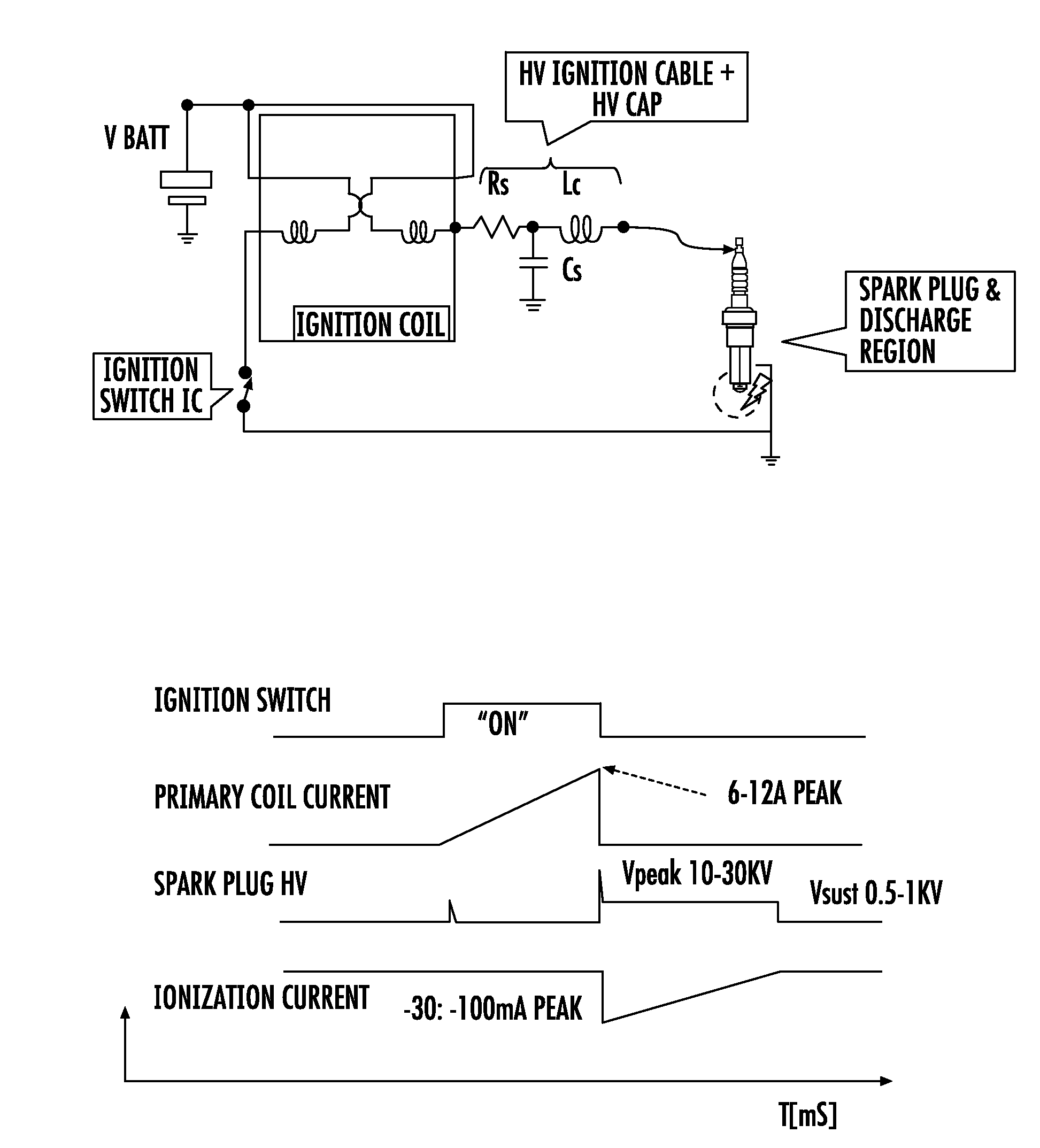
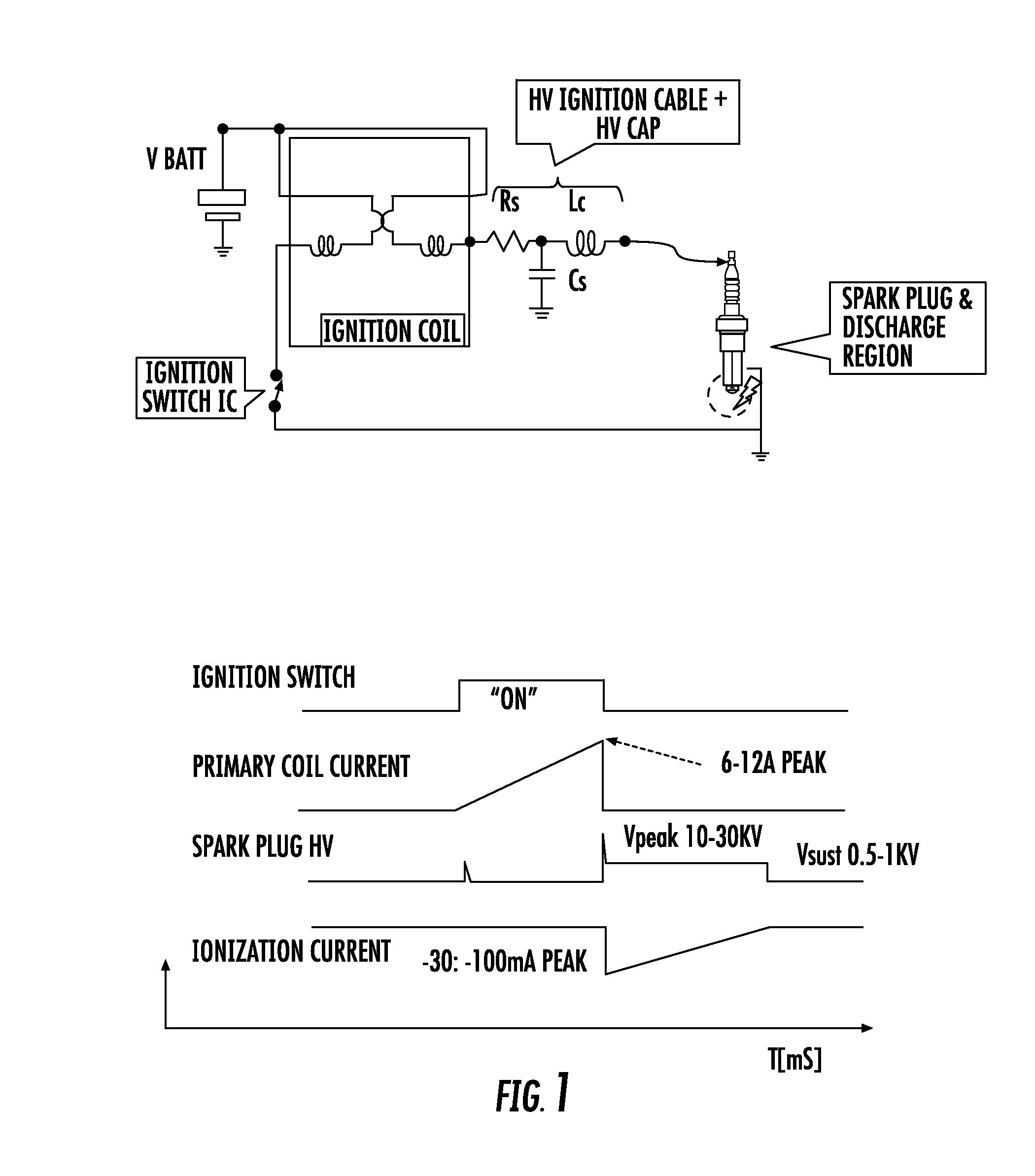
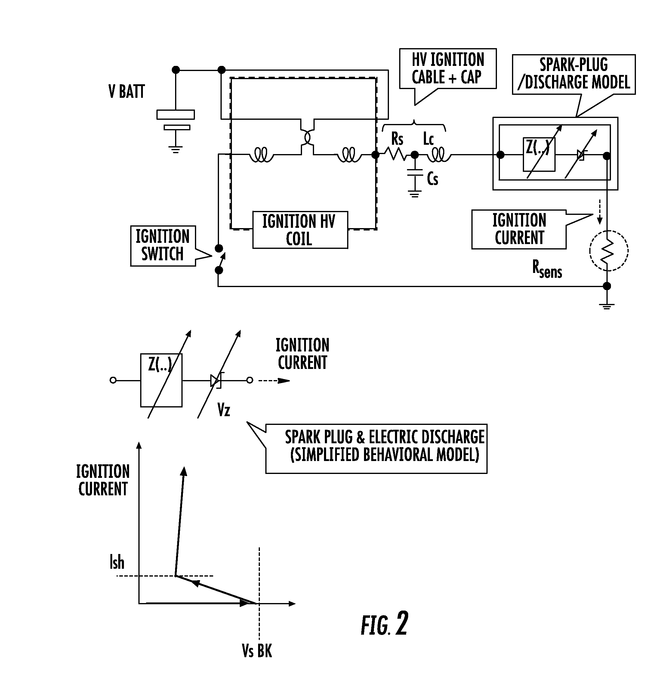
[0057]A typical spark plug circuit and the associated timing diagram of the idealized waveforms of the significant electrical signals and typical signal amplitudes are shown in FIG. 1, whilst a simplified correspondent analytical model of the electrical spark plug circuit of FIG. 1 further including a current sense resistor in series to the ground electrode of the spark plug and the basic current-voltage characteristic are shown in FIG. 2. FIG. 3a is a simulated waveform of the voltage drop on a 50 Ω current sensing resistor of the analytical model considered of FIG. 2.

[0058]FIG. 3b shows a portion of the simulated decaying oscillatory ionization part of the current signal during a full ionization phase of the combustion process.

[0059]FIG. 3c is a logarithmic scale illustration of spectral contents in the frequency domain of the simulated decaying oscillatory ionization part of the ionization current calculated by Fast Fourier Transform.

[0060]A typical waveform (filtered from high f...


PUM


Abstract

The pressure in the combustion chamber of an electronically controlled spark plug ignition engine may be estimated in real time mode without specific sensors by processing sensed ionization current data to calculate features of the current waveform proven to be correlated to the pressure inside the engine cylinders and correlating them on the basis of a look up table of time invariant correlation coefficients generated through a calibration campaign of tests on a test engine purposely equipped with sensors. A mathematical model of the electrical and physical spark plug ignition system and combustion chamber of the engine is refined during calibration by iteratively testing the interactive performance of correlation coefficients of related terms of a mathematical expression of the model and comparing the expressed pressure value with the real pressure value as measured by a sensor.

Description

CROSS REFERENCE TO RELATED APPLICATIONS[0001]This application claims the priority benefit of Italian Patent Application No. MI2013A000750, filed May 9, 2013, and which application is hereby incorporated by reference to the maximum extent allowable by law.BACKGROUND[0002]1. Technical field[0003]The present disclosure relates in general to data acquisition and processing for real time diagnostic and / or control of the functioning of a spark ignition internal combustion engine through evaluation of operating parameters and in particular to “sensorless” evaluation of the pressure in the combustion chamber from waveform feature data of the sensed ionization current.[0004]2. Discussion of the Related Art[0005]In the last decades, ionization current diagnostics has proven itself to be an effective approach in investigating the mechanism of fuel combustion and optimizing spark-ignition (SI) engine control.[0006]Monitoring of ionization current waveform in SI engines fueled with gasoline or d...

Claims


Application Information

Patent Timeline
IPC IPC(8): F02P17/12G01M15/09
CPCF02P17/12G01M15/09F02D41/22F02D41/2422F02D41/2425F02D35/024Y02T10/40F02D35/021G01M15/042
Inventor PATTI, DAVIDEGIUSEPPEPAPARO, MARIO
Owner STMICROELECTRONICS SRL
Learn More