Image sensor

a technology of image sensor and photoelectric conversion element, which is applied in the direction of optical radiation measurement, radiation control device, instruments, etc., can solve the problems of reducing the incident efficiency of the blue the space of the partition wall is relatively small, and the incident efficiency of the green light on the photoelectric conversion element is reduced. , to achieve the effect of improving the incident efficiency of the photoelectric conversion elemen

Inactive Publication Date: 2014-11-20
FUJIFILM CORP
View PDF4 Cites 10 Cited by
  • Summary
  • Abstract
  • Description
  • Claims
  • Application Information

AI Technical Summary

Benefits of technology

[0020]According to the image sensor of the present invention, which is an image sensor provided with a partition wall at the boundaries of color filters having different spectral characteristics, the partition wall is formed so as to be narrower in space on the exit side of the light than on the incident side of the light. This may inhibit the action that draws light transmitted through the partition wall into an adjacent color filter at an area of the partition wall having a wide space on the light incident side, so that the incident efficiency of light transmitted through each color filter on the photoelectric conversion element may be improved. In the meantime, the spectral characteristics based on the original absorption of the color filters may be maintained at an area of the partition wall having a narrow space on the light incident side, so that color mixing may be inhibited.

Problems solved by technology

For example, this action may cause a problem that the light incident on a blue (B) filter is incident on a green (G) filter via the partition wall and the incident efficiency of the blue light on the photoelectric conversion element is reduced, and light incident on a green (G) filter is incident on a red (R) filter via the partition wall and the incident efficiency of the green light on the photoelectric conversion element is reduced.
This problem may occur when the space of the partition wall is relatively small and appears significantly, in particular, when the space of the partition wall is about the wavelength of the incident light or less.
On the other hand, if the space of the partition wall is too wide, the light transmitted through the partition wall is incident on photoelectric conversion elements without transmitting through each color filter, thereby causing the problem of color mixing.

Method used


Image

  • Image sensor
  • Image sensor
  • Image sensor

Examples


Embodiment Construction

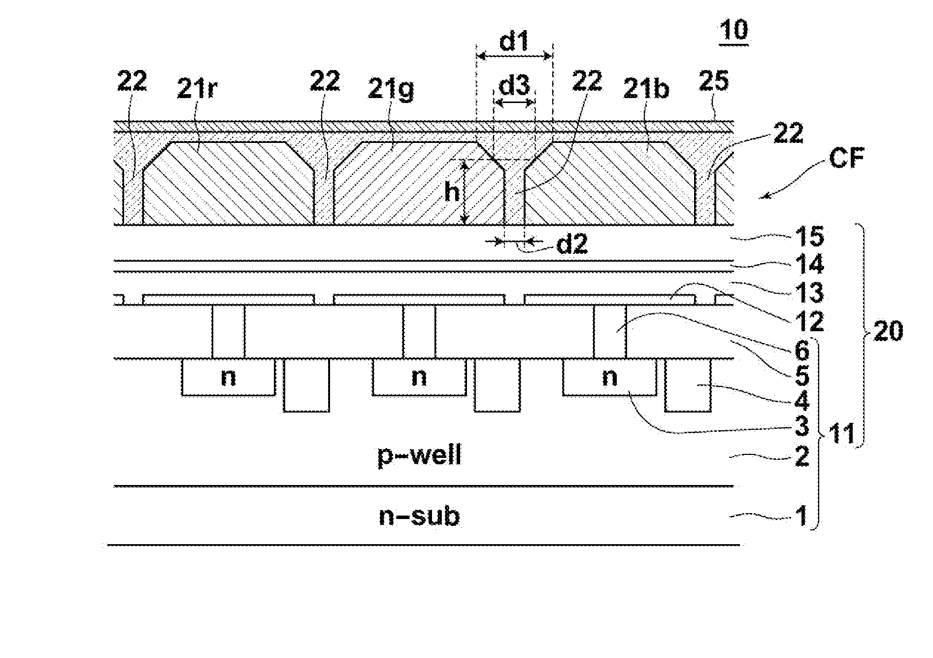
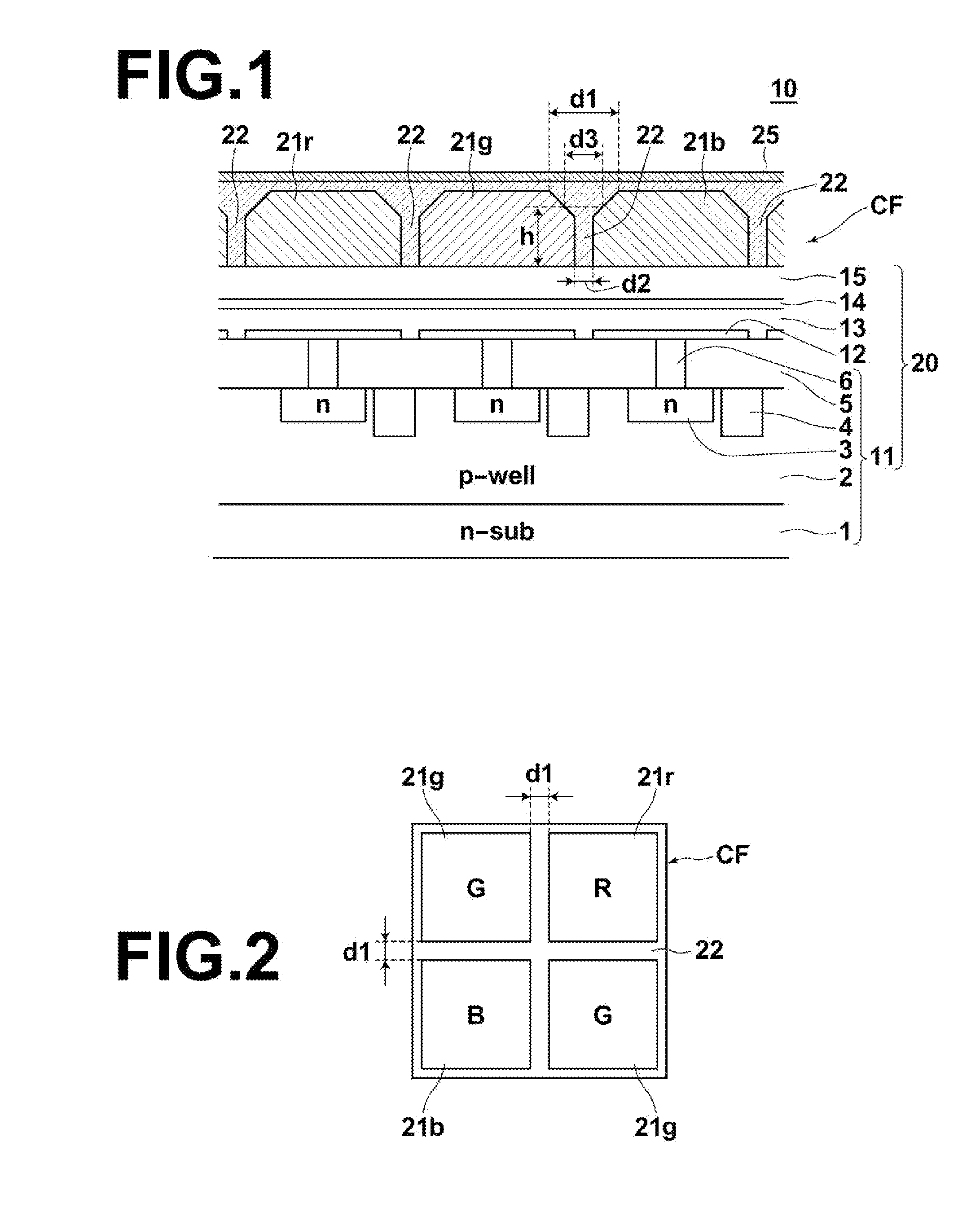
[0032]Hereinafter, an embodiment of the image sensor of the present invention will be described in detail with reference to the accompanying drawings. FIG. 1 is a cross-sectional view of the image sensor of the present embodiment, illustrating a schematic configuration thereof.

[0033]As illustrated in FIG. 1, the image sensor 10 of the present embodiment includes a semiconductor circuit board 11, a plurality of pixel electrodes 12 formed on the semiconductor circuit board 11 in a two-dimensional array, a photoelectric conversion layer 13 formed continuously on the plurality of pixel electrodes 12 with an organic material, a common electrode (upper electrode) 14 which is the counter electrode opposite to the plurality of pixel electrodes 12 formed on the photoelectric conversion layer 13 as a single layer. Further, a transparent insulating layer 15 is formed on the upper electrode 14, and from the semiconductor circuit board 11 to the insulating layer 15 are collectively referred to a...


PUM


Abstract

An image sensor having a plurality of photoelectric conversion elements that receive light and convert the light to electric charges, color filter layers having different spectral characteristics, each being provided corresponding to each of the photoelectric conversion elements, and a partition wall having a lower refractive index than that of the color filter layers provided at the boundary of each color filter layer. The image sensor is formed such that a space of the partition wall on the light exit side is narrower than a space of the partition wall on the light incident side.

Description

CROSS-REFERENCE TO RELATED APPLICATIONS[0001]This application is a Continuation of PCT International Application No. PCT / JP2013 / 000324 filed on Jan. 23, 2013, which claims priority under 35 U.S.C. §119 (a) to Japanese Patent Application No. 2012-017507 filed on Jan. 31, 2012. Each of the above application(s) is hereby expressly incorporated by reference, in its entirety, into the present application.BACKGROUND OF THE INVENTION[0002]1. Technical Field[0003]The present invention relates to an image sensor which includes a plurality of photoelectric conversion elements, each having a color filter with a partition wall at the boundary thereof.[0004]2. Background Art[0005]Heretofore, various types of image sensors, such as CCD, CMOS, and the like, have been proposed in which a plurality of photoelectric conversion elements that convert light to an electric charge is disposed.[0006]As such image sensors, those provided with color filters are known. For example, an image sensor provided wi...

Claims


Application Information

Patent Timeline
Patent Type & Authority Applications(United States)
IPC IPC(8): G01J1/02H01L27/146G01J1/04
CPCG01J1/0295H01L27/14621G01J1/0492G02B5/201
Inventor TANI, TAKEHARU
Owner FUJIFILM CORP
Why Eureka
Try Eureka