
Shield grounding device

a shield and grounding technology, applied in the direction of earthing wire/cable arrangement, electrical equipment, connection contact material, etc., can solve the problems of rosin joint, rosin joint, rosin joint, welding fault, etc., to reduce site operation difficulty, improve grounding resistance, and poor grounding effect

Active Publication Date: 2014-12-11
ZHENFA ENERGY GRP
View PDF3 Cites 3 Cited by
  • Summary
  • Abstract
  • Description
  • Claims
  • Application Information

AI Technical Summary

Benefits of technology

[0006]An object of the present invention is to provide a shield grounding device for solving problems of a increased grounding resistance and a poor grounding effect which are caused by unstable welding quality between grounding electrodes and flat irons thereof, while lowering site operation difficulty, decreasing labor intensity, increasing labor efficiency, so as to lower cost.
[0013]Compared to conventional grounding devices, advantages of the present invention are as follows. The two shield connection boards vertical to each other are respectively connected to the top portion of the grounding angle steel, and the fixing holes are drilled on the shield connection board. During site operation, the shield connection boards and the fixing holes are connected to grounding wires or the laminated board by bolts and nuts. Or the shield connection boards on the grounding angle steel and the fixing holes on the shield connection boards are connected to other grounding angle steels in any possible forms by bolts and the flat irons, for forming a grounding set, a grounding group, or a grounding grid with any shape as required. On-site vertical welding is no longer needed, and the problems of the increased grounding resistance and the poor grounding effect caused by unstable vertical welding quality are solved. Besides, the site operation difficulty is sufficiently lowered, the labor efficiency is increased, the labor intensity is decreased, and the labor cost is lowered. The surface-roughened zinc layers are coated on the surfaces of the shield connection board and the flat iron; the zinc layer is the roughened surface in the form of the irregular micro hills, which effectively increases a contact area and reduces a contact resistance for further reducing the grounding resistance. In addition, during mechanical pressure injection of the grounding angle steel, the supporting angle steel pieced and welded with the top portion of the grounding angle steel has a sufficient supporting effect, in such a manner that destruction of the ground angle steel and the shield connection board caused by punching and pressing is reduced. The streamline protector is welded at the bottom portion of the shield connection board for protection during the mechanical pressure injection. If depth of the mechanical pressure injection is large, the whole-length bearing bars welded with the connecting portion of the flange of the ground angle steel along the length direction are able to effectively strengthen the ground angle steel.

Problems solved by technology

The welding pool is easy to be discontinuous because of being vertical during the vertical welding, which will lead to welding fault, missing welding, rosin joint, etc.
However, during site operation of grounding grid, the rosin joint can easily lead to disassembly of the grounding wire steel frame, which increases the grounding resistance and lowers the grounding quality.
Furthermore, even parameter requirements of the grounding electrode may not be satisfied.
Therefore, the grounding resistance cannot be guaranteed, and the grounding effect is poor.
Besides, when all the grounding electrodes are welded to each other through the flat irons, especially when the grounding electrodes form a square-mesh grounding grid, the grounding electrodes and the flat irons outside and inside the grounding frame are longitudinally (vertically) and latitudinally (horizontally) welded with more than three surfaces, which is large in workload, difficult in operation, high in labor intensity, and low in labor efficiency.
In addition, during site operation of the conventional grounding device, wiring and welding are carried out manually, which is inefficient, difficult and expensive.

Method used


Image

  • Shield grounding device
  • Shield grounding device
  • Shield grounding device

Examples


Embodiment Construction

[0025]A shield grounding device according to a preferred embodiment of the present invention is illustrated, comprising:

[0026]a grounding angle steel 1;

[0027]a flat iron 9 mounted on a top portion of the shield grounding device; and

[0028]a laminated board 5 connected to overground wires;

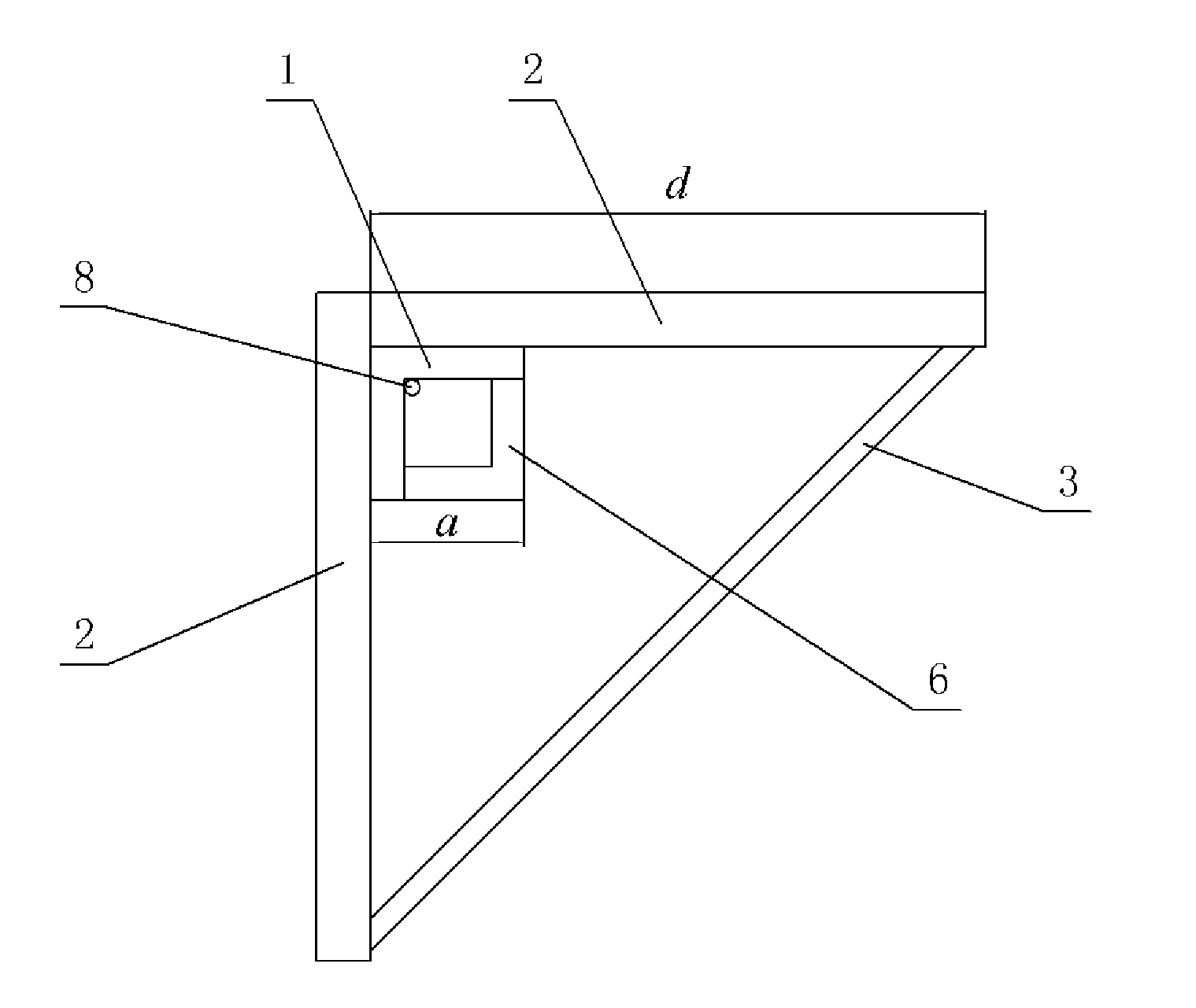
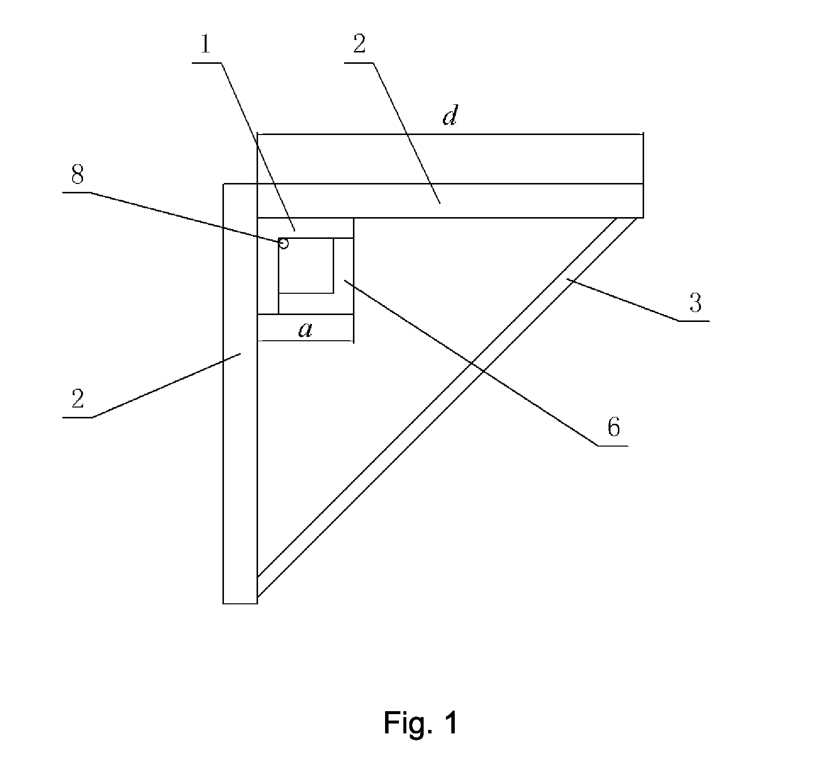
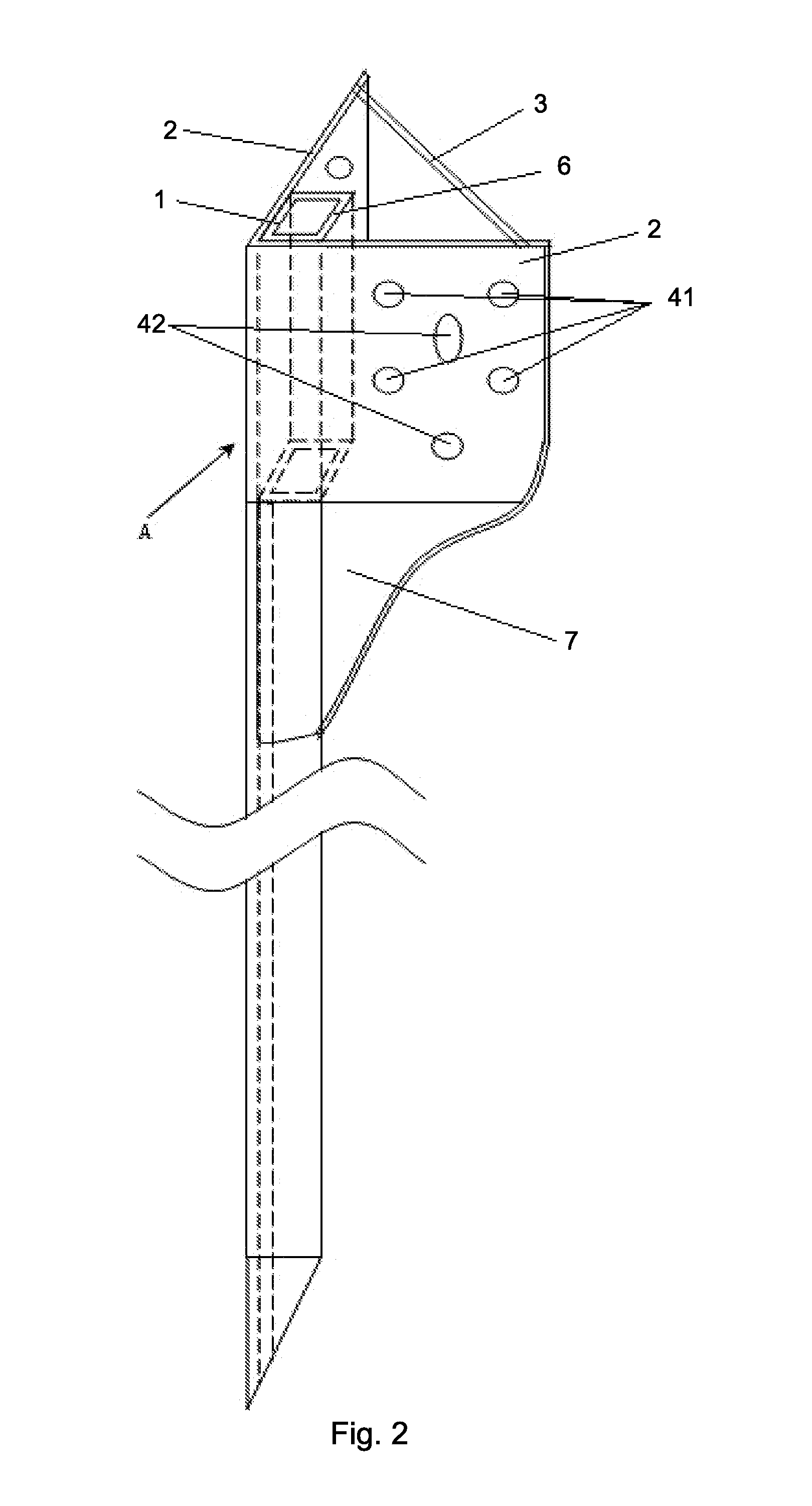
[0029]wherein two shield connection boards 2 vertical to each other are respectively connected to two external surfaces of a top end of the grounding angle steel 1; the shield connection boards 2 are vertically positioned by a locating supporter 3; and fixing holes 4 are drilled on the shield connection boards 2 for connecting the flat iron 9 or the laminated board 5.

[0030]Preferably, the shield connection boards 2 are both square, a side length a thereof is at least four times of a width d of a flange of the grounding angle steel 1. Six the fixing holes 4 are drilled on each of the shield connection boards 2. The fixing holes are respectively four flat iron fixing holes 41 and two laminated board fi...


PUM


Abstract

A shield grounding device includes: a grounding angle steel (1); a flat iron (9) mounted on a top portion of the shield grounding device; and a laminated board (5) connected to overground wires; wherein two shield connection boards (2) vertical to each other are respectively connected to two external surfaces of an top end of the grounding angle steel, the shield connection boards are vertically mounted on each other by a locating supporter (3), fixing holes (4) are drilled on the shield connection boards for connecting the flat iron and the laminated board. The device solves problems of conventional grounding devices that a grounding resistance is increased and a grounding effect is poor caused by unstable welding quality of grounding electrodes and the flat iron. Besides, site operation difficulty is sufficiently lowered, labor intensity is decreased, and labor efficiency is increased, in such a manner that a cost is lowered.

Description

CROSS REFERENCE OF RELATED APPLICATION[0001]This is a U.S. National Stage under 35 U.S.C 371 of the International Application PCT / CN2012 / 074155, filed Apr. 17, 2012, which claims priority under 35 U.S.C. 119(a-d) to CN 201210017322.8, filed Jan. 19, 2012.BACKGROUND OF THE PRESENT INVENTION[0002]1. Field of Invention[0003]The present invention relates to anti-lightning and anti-static devices, and a technical field of safety grounding, and more particularly to a shield grounding device.[0004]2. Description of Related Arts[0005]For most of the conventional grounding devices, grounding electrodes are buried in a pre-dug pit on the scene. The grounding electrode is connected to a laminated board which is connected to overground wires, through a flat iron welded with a top portion thereof, or to other grounding electrodes for forming a grounding frame or a grounding group. The disadvantages are as follows. The flat iron on the grounding electrode is vertically welded instantly. The weldi...

Claims


Application Information

Patent Timeline
IPC IPC(8): H02G7/22H01B5/02
CPCH01B5/02H02G7/22H01R4/66
Inventor MAO, JIANSHENG
Owner ZHENFA ENERGY GRP
Learn More