Solder alloys

a technology of alloys and solders, applied in the direction of welding/cutting media/materials, solventing apparatus, manufacturing tools, etc., can solve the problems of high-tin (sn) solders that inherently do not work over 200° c, are susceptible to thermal fatigue failure, and other solders such as hard au-containing solders are expensive and other problems, to achieve the effect of increasing the thermal conductivity of the solder according to the present technology

Inactive Publication Date: 2014-12-11
THE RES FOUND OF STATE UNIV OF NEW YORK
View PDF5 Cites 16 Cited by
  • Summary
  • Abstract
  • Description
  • Claims
  • Application Information

AI Technical Summary

Benefits of technology

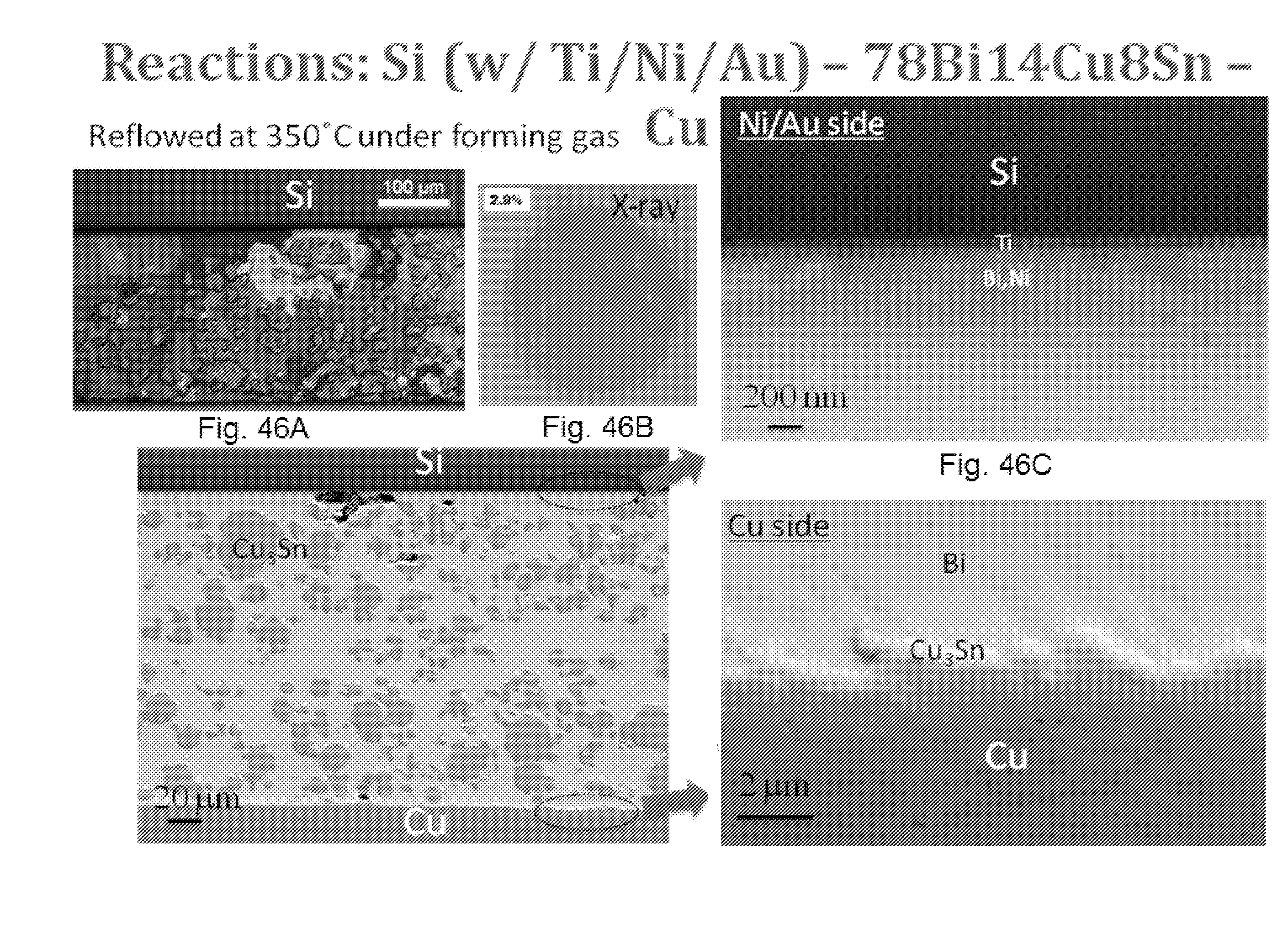
[0048]Once reflowed into the joined area between the die and the substrate, a thermal conductivity of the solder according to the present technology becomes greater than the corresponding bulk bismuth solders and comparable to high-Pb based solders. The bonded dies using these solder alloys have a shear strength comparable to high-Pb based solders and one commercially available Bi solder.

Problems solved by technology

High-tin (Sn) solders inherently do not work over 200° C. due to their approaching too closely their melting points.
Other solders such as hard Au-containing solders are expensive and are susceptible to thermal fatigue failure.

Method used


Image

  • Solder alloys
  • Solder alloys
  • Solder alloys

Examples


Embodiment Construction

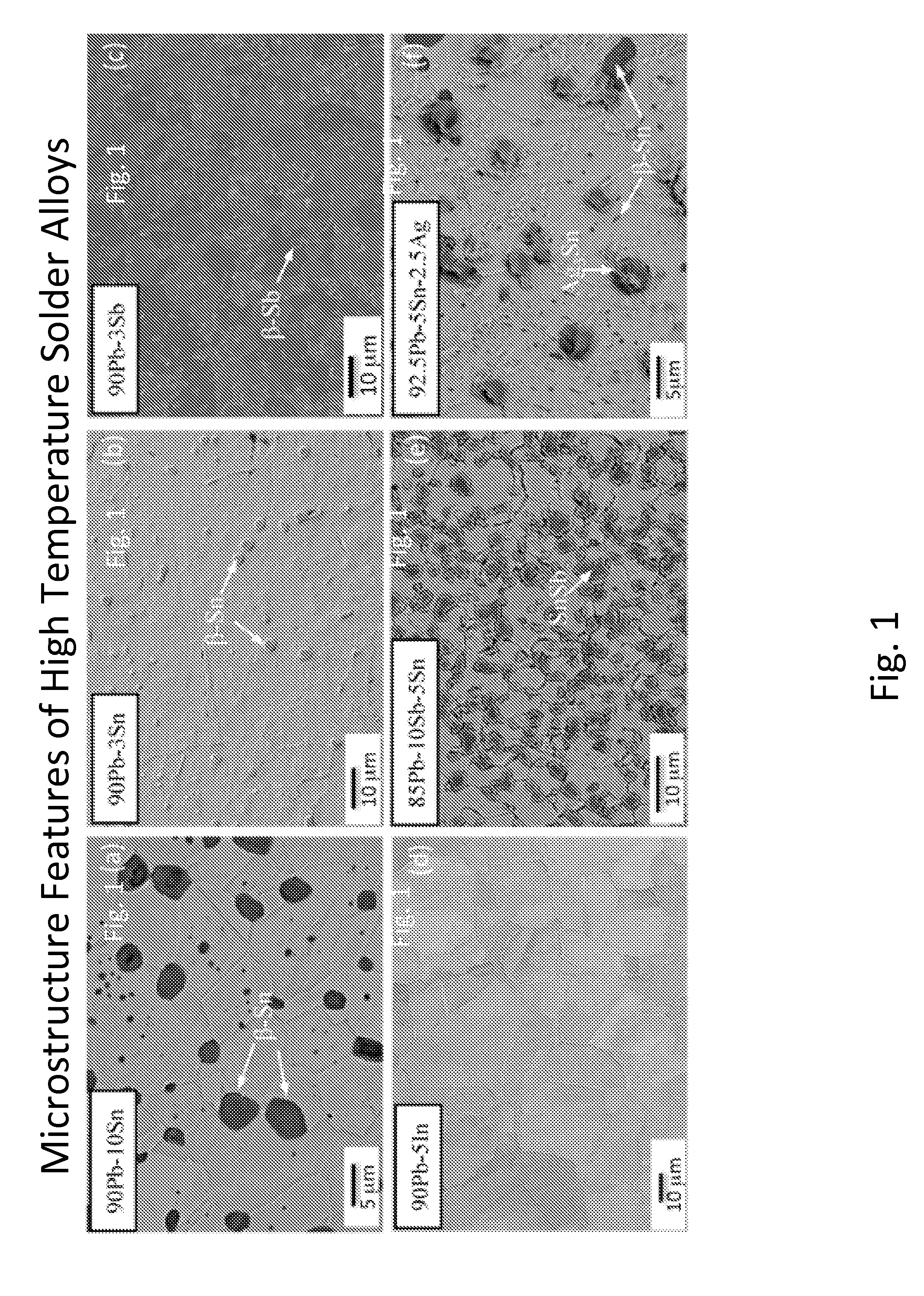
[0083]Table 1 shows properties of various high temperature solders:

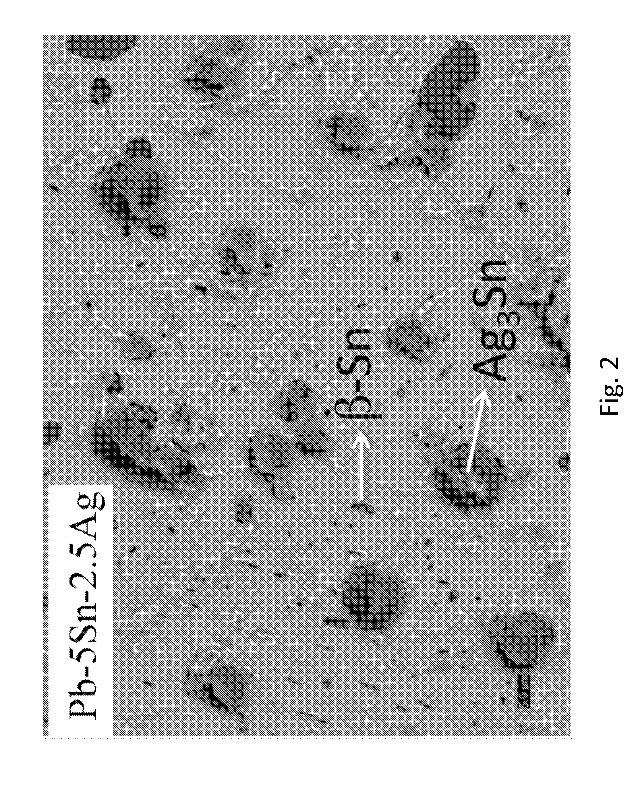
TABLE 1High Temperature Solder AlloysLiquidusSolidusSolder AlloysTemp (° C.)Temp (° C.)Notes95Sn 5Sb240235Pb-freeprocess temp >300° C.,soldernot compatible for >200° C.90Sn10Sb272250Pb-freeprocess temp >300° C.,soldernot compatible for >200° C.85Pb10Sb 5Sn255245SuperplasticProcess temp >350° C.,Alloyenvironmental concerns90Pb10Sn301268Single phaseProcess temp >350° C.,aboveenvironmental concerns135° C.92.5Pb 5Sn 2.5Ag296287β-Sn, IMCProcess temp >350° C.,environmental concerns93Pb 3Sn 2Ag2In304—β-Sn, IMC,Process temp >350° C.,solidenvironmental concernssolution92.5Pb 5In 2.5Ag310300IMC, solidProcess temp >350° C.,solutionenvironmental concerns95Pb 5In313300Single phaseProcess temp >350° C.,alloyenvironmental concerns97Pb 3Sb320300β-SbProcess temp >350° C.,environmental concerns97Pb 3In320315Single phaseProcess temp >350° C.,alloyenvironmental concerns97Pb 3Sn321315β-SnProcess temp >350° C.,environmental concerns78Bi14...


PUM

PropertyMeasurementUnit
solidus temperatureaaaaaaaaaa
liquidus temperatureaaaaaaaaaa

Abstract

A solder comprising a bismuth matrix, between about 5-24% copper; and about 0.5-36% tin or antimony or zinc; having a solidus temperature of ≧271° C., a reflow temperature of ≦375° C., and at least one intermetallic composition precipitate comprising copper and at least one of tin, antimony and zinc substantially excluding bismuth formed within the solidus phase.

Description

CROSS REFERENCE TO RELATED APPLICATION[0001]The present application claims benefit of priority from U.S. Provisional Patent Application No. 61 / 831,504, filed Jun. 5, 2013, the entirety of which is incorporated herein by reference in its entirety.FIELD OF THE INVENTION[0002]The present invention relates to high temperature solder compositions and methods for use, and more particularly lead-free, bismuth solders.BACKGROUND OF THE INVENTION[0003]Power electronics that operate at temperatures over 200° C. require die attach materials with higher performance compared to traditional solders and epoxy-based adhesives in order to operate reliably. As power dissipation of components increases and overall package size decreases, engineers must innovate to ensure components don't overheat. Devices that run cooler last longer. In addition, in advance of forecasted government mandates, there is a growing focus on developing high-melting point (HMP) solders that do not contain lead (Pb).[0004]Sol...

Claims


Application Information

Patent Timeline
Patent Type & Authority Applications(United States)
IPC IPC(8): B23K35/26B23K1/20
CPCB23K1/20B23K35/264B23K35/0222B23K35/0244B23K35/26B23K35/262B23K35/302B23K35/304
Inventor CHO, JUNGHYUN
Owner THE RES FOUND OF STATE UNIV OF NEW YORK
Why Eureka
Try Eureka