Low fault current isolator system

a fault current isolator and low fault technology, applied in the direction of coupling device connection, instruments, sustainable buildings, etc., can solve the problems of inability to distinguish low fault current (high impedance fault) from normal load current, difficult to isolate with present technology, etc., to achieve low cost, safe and fast

Active Publication Date: 2014-12-11
ELECTRICAL MATERIALS
View PDF4 Cites 29 Cited by
  • Summary
  • Abstract
  • Description
  • Claims
  • Application Information

AI Technical Summary

Benefits of technology

[0029]These features are provided in a high-speed, low cost automatic tripping device for clearing a high impedance fault such as, for example, a downed high voltage conductor within a utility power distribution grid which includes a solenoid receiver in combination with a coiled spring. Responsive to a received direct or remote (RF) signal representing the fault condition, the solenoid releases the coiled spring which is under tension from a latched ...

Problems solved by technology

High impedance, low current faults, such as a downed distribution line conductor in an electric utility distribution network which is contacting a poor conductive earth composite, have proven to be difficult to isolate with present technology.
A particularly difficult situation for detecting a high impedance fault in an electrical distribution system involves a live conductor downed, but intact, and grounded through a poor conducting medium such as sand, rock, concrete, snow, blacktop or a tree.
Overcurrent protection devices are, however, unable to distinguish low fault currents (high impedance faults) from normal load currents because trip settings for these devices are typically set at 125 to 250 per cent of maximum estimated peak load current.
A hazardous condition for the public is created when energized high voltage con...

Method used


Image

  • Low fault current isolator system
  • Low fault current isolator system
  • Low fault current isolator system

Examples


Embodiment Construction

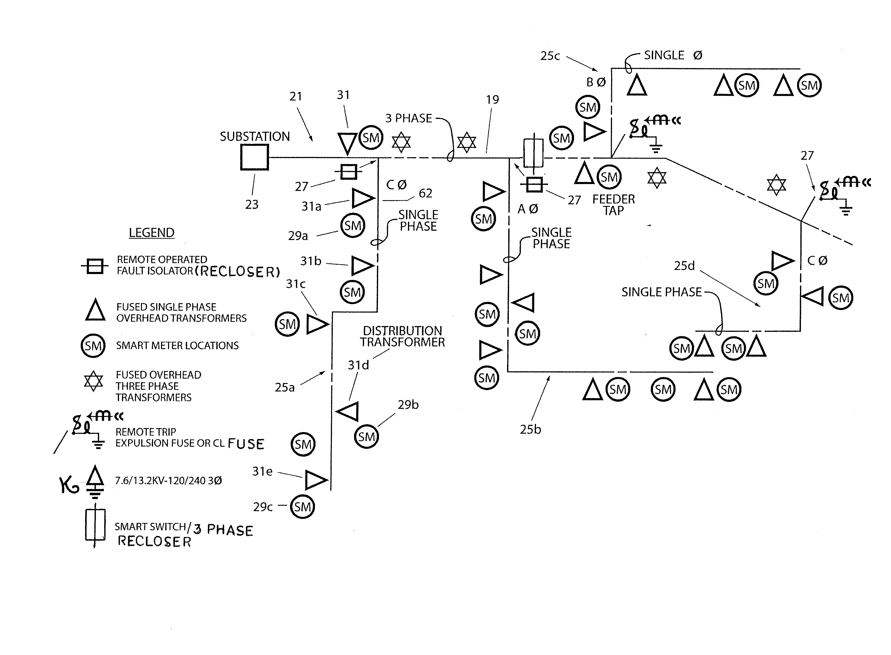
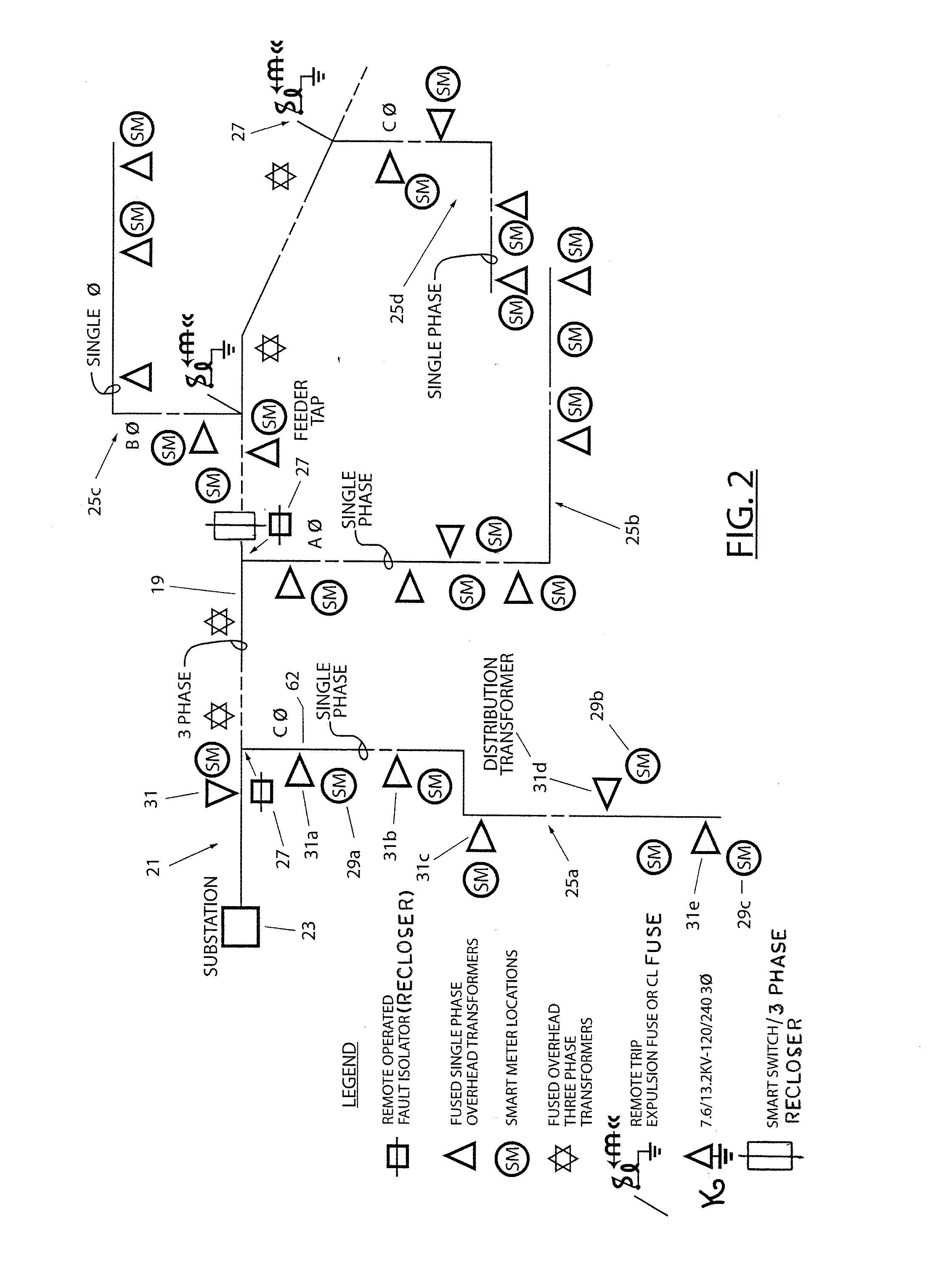
[0044]Referring to FIG. 2, there is shown a simplified schematic diagram of a portion of an electrical distribution system 21 incorporating an arrangement for isolating high impedance faults with low current in accordance with the present invention. The electrical power distribution system 21 includes a substation 23 and a three-phase main feeder line 19. Coupled to the main feeder line 19 are plural branches 25a, 25b, 25c and 25d, each of which receives a single phase in the three phase power distribution system 21. Each of the branches is essentially the same, with additional details of only the first branch 25a provided herein for simplicity, with the same identifying numbers used in each of the branches to identify the same components in these branches. The first branch 25a includes a plural distribution transformers 31a, 31b, 31c, 31d and 31e, each of which is shown as a triangle in the figure. The first branch 25a further includes a plurality of smart meters, three of which ar...


PUM


Abstract

A low fault current isolation arrangement senses a loss of voltage and automatically isolates and de-energizes a down live primary wire if overcurrent protection devices have not cleared the high impedance fault in an electric power distribution network. Incorporating an operator selectable time delay response, the low fault current isolation arrangement permits overcurrent protection devices to attempt to detect and shut down the affected conductor, and then isolates and shuts down the low current fault if the overcurrent devices are not successful. The isolation arrangement continuously monitors AC voltage as remotely provided by smart meters even after a fault location is de-energized, and serves as a back up, and not as a replacement, for existing overcurrent protection schemes. A host computer operates in conjunction with plural smart meters each coupled to an associated customer distribution transformer in conjunction with the fault isolator to detect and shut down high impedance faults.

Description

FIELD OF THE INVENTION[0001]This invention relates generally to apparatus for sensing, isolating and de-energizing a downed alternating current electric utility primary distribution circuit conductor which has developed into a high impedance fault which overcurrent protection devices or high impedance detection systems have been unable to clear. This type of high impedance fault condition may also occur when a high voltage conductor is down and grounded via a high impedance primary ground producing backfeed through a common connection of three single phase transformers. In this latter situation, the three single phase transformer windings of different phases are the source of a low level backfeed fault current and high voltage on the downed conductor.[0002]This invention also relates to an adapter for mounting an out-of-service electric utility watthour meter to a disconnected customer's electric meter socket, where the meter remains source side energized to continue carrying out of...

Claims


Application Information

Patent Timeline
IPC IPC(8): H02H3/10G01R1/04H02H3/093
CPCH02H3/10H02H3/093G01R1/04H02H1/0092H02H7/28G01R1/0408G01R22/065H02H1/0061H02H7/263G01R31/52Y04S20/14Y02B90/20H01R13/05H01R13/71H01H85/041H01H85/38
Inventor O'REGAN, TIMOTHY M.O'REGAN, TIMOTHY J.HAYES, THOMASSEVERSON, KEVIN J.
Owner ELECTRICAL MATERIALS
Why Eureka
Try Eureka