Fuel Air Premix Chamber For a Gas Turbine Engine

Active Publication Date: 2014-12-18
TEETAB JOSEPH MICHAEL
View PDF5 Cites 22 Cited by
  • Summary
  • Abstract
  • Description
  • Claims
  • Application Information

AI Technical Summary

Benefits of technology

[0009]In view of the foregoing disadvantages inherent in the known types of RQL combustors now present in the prior art, the present invention provides a new radially staged RQL combustor with tangential fuel premixers construction wherein the same can be utilized for providing a internal combustion energy device for a gas turbine engine to yield low emission, reduced cost, improved durability, mulifuel use including low BTU gas—bio fuels, good flame stability at any power settings and ease of starting. The general purpose of the present invention, which will be described subsequently in greater detail, is to provide a new radially staged RQL combustor with tangential fuel air premix chambers that has many novel features and result in a new radially staged RQL combustor which is not anticipated, rendered obvious, suggested, or even implied by any of the prior art, either alone or in any combination thereof. To attain this, the present invention generally comprises a combustor assembly, having a primary combustion zone, secondary

Problems solved by technology

The main challenge with a combustor is controlling combustion flame temperature which by most part dictates emissions species levels of NOx (oxides of nitrogen, NO+NO2), CO (carbon monoxide) and UHC (unburned hydrocarbons).
To attain this approximate narrow band of flame temperatures, variable geometry means to the air supply could be incorporated but would add complexity in hardware control methods and maintenance yielding an increase of cost.
U.S. Pat. Nos. 5,894,720 and 5,966,926 LPP type combustors offer low emission at high end power level and incorporates staged premix fuel/air nozzles to assist in the reduction of emission at off design power or reduced power requirements and aide in the combustion flame stability, but too lean of a F/A ratio would cause combustor flame extinction.
Whittle in early years of gas turbines ˜1936 attempted to use fuel delivery in

Method used


Image

  • Fuel Air Premix Chamber For a Gas Turbine Engine
  • Fuel Air Premix Chamber For a Gas Turbine Engine
  • Fuel Air Premix Chamber For a Gas Turbine Engine

Examples


Example

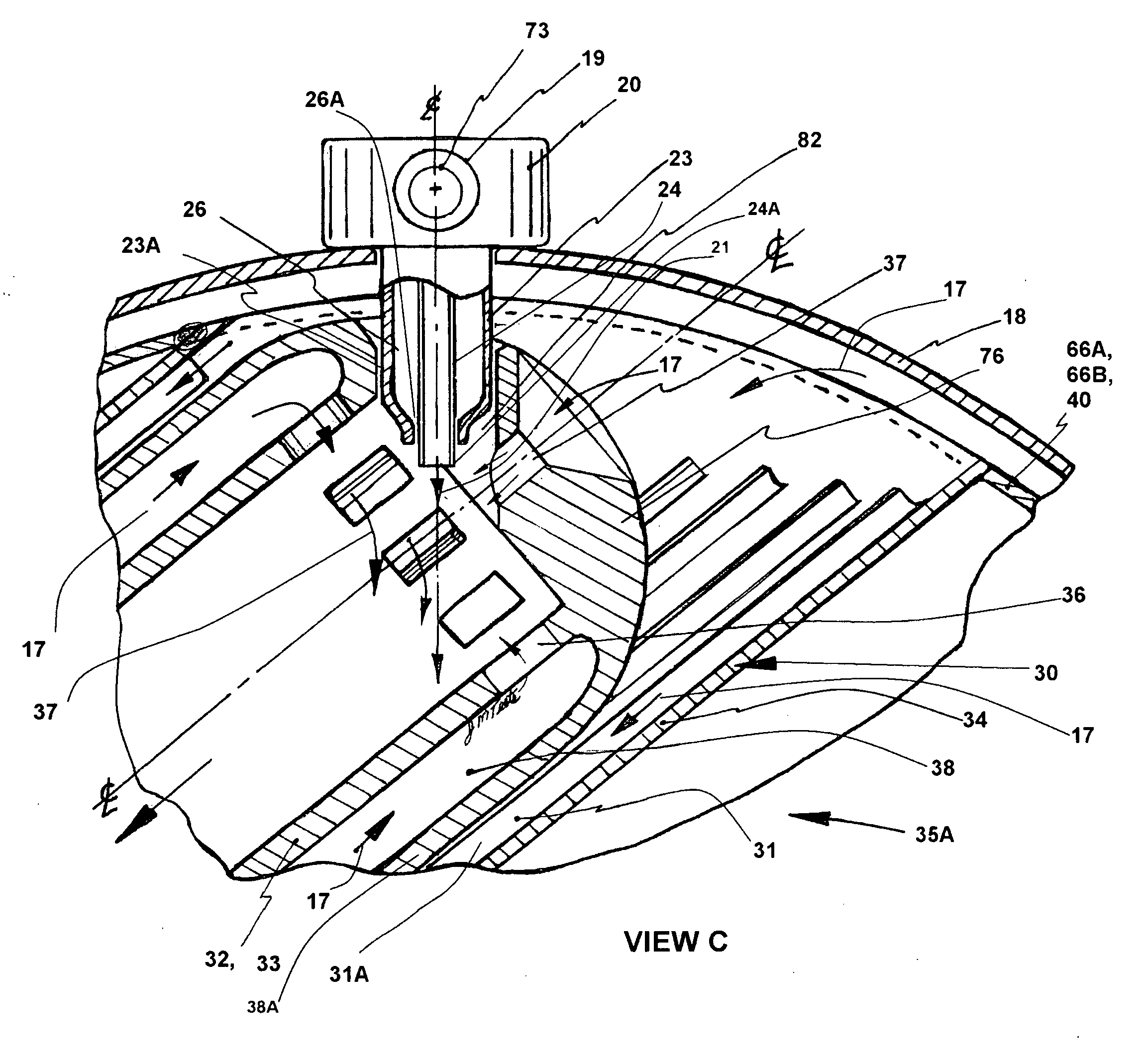
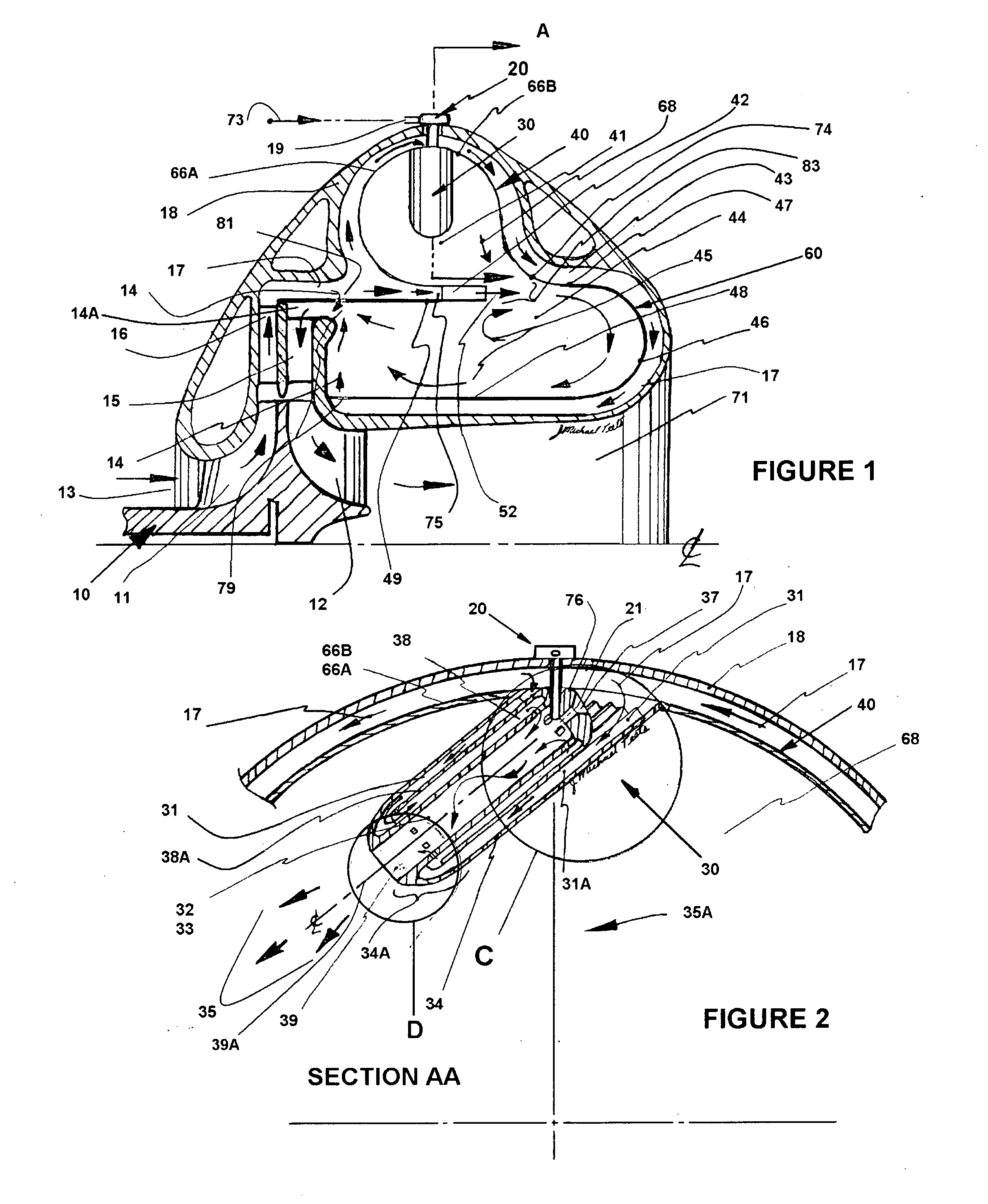
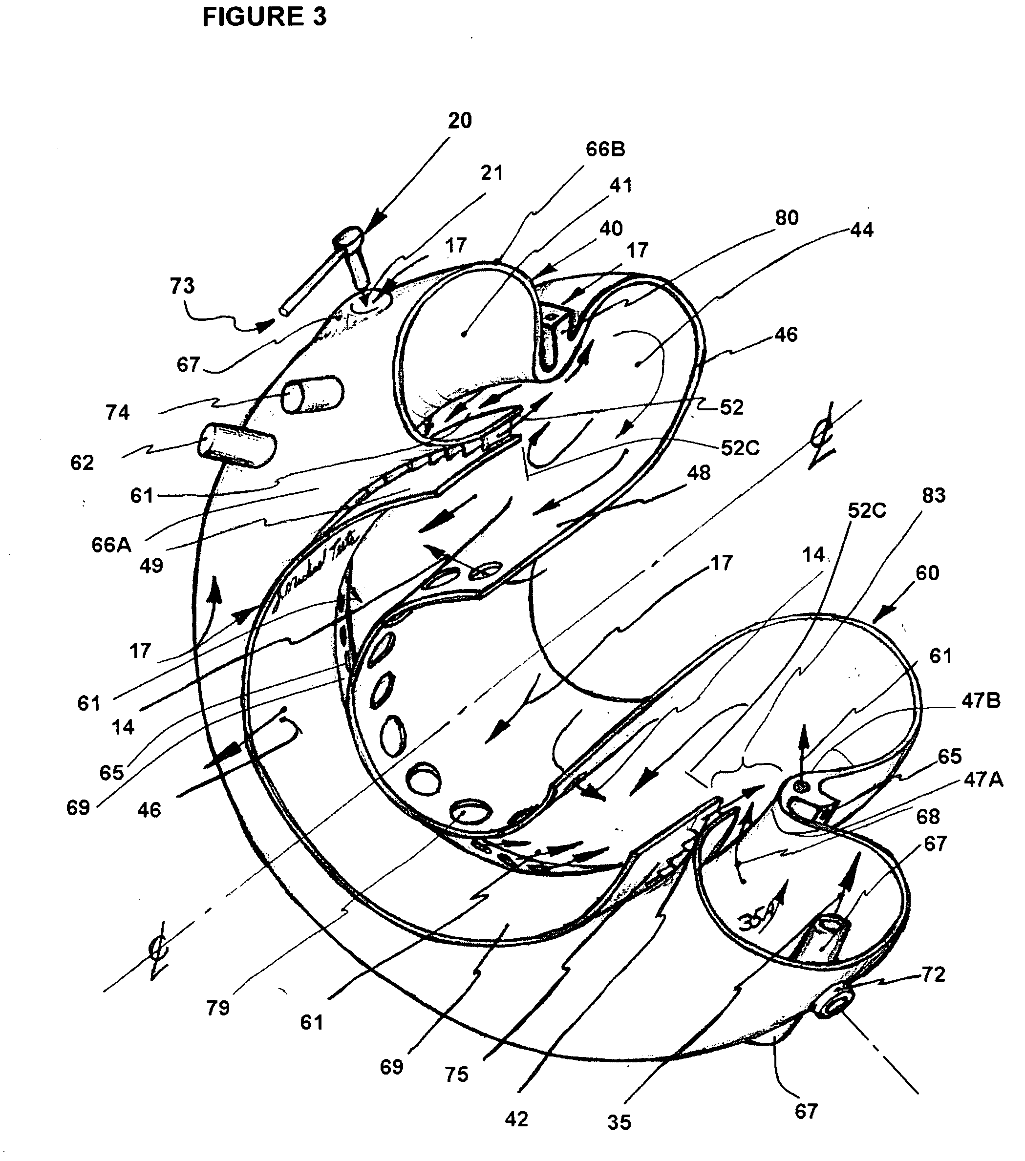
[0033]Turning now descriptively to the drawings, in which similar reference characters denote similar elements throughout the several views, the attached figures illustrate a radially staged RQL combustor assembly with tangential fuel premix-vaporizer chambers, and comprise of: a primary combustion zone with fuel injection means, tangentially oriented primary fuel air premix chamber, a secondary air supply area, a reduced combustor flow area to receive secondary air supply for fuel / air premixing, a secondary combustion zone, a dilution air supply area, a dilution zone.

[0034]This Rich burn-Quick quench-Lean burn (RQL) combustor invention having a toroidal geometry primary combustion zone with tangential fuel air premix chamber is generally positioned radially outboard of the secondary combustion zone. The fuel air premix chamber 30 is a longitudinally elongated tubular form assembly with an outer tube 34 having internal cooling means 31A and a co-axial inboard fluid turning end 34A a...


PUM


Abstract

Fuel/air premixing chambers are applied to a gas turbine combustor RQL or LPP type integrated to the combustor with extension into the combustion zone. An integral heat exchange structure cools the premix chamber outer wall, preheating the compressor air supply as it passes into an inner central longitudinal premix tube preheating also the fuel and F/A mixture for improved mixedness, low emissions combustion and low differential combustor pressure.
The F/A premix flow thru the central longitudinal tubes yields an exiting spouting velocity into the primary combustion zone for swirl/circumferential flow combustion yielding flame stability. Circumferentially close spaced premixing chambers about the combustor outer wall, are tangentially positioned for internal combustion hot gas flow, preheating the adjacent premix chamber and generates internal sweeping hot gas flow preventing combustion chamber carbon issues. Incorporates low pressure fuel injection into a central longitudinal tube for reduced cost and system simplicity.

Description

[0001]This application claims benefit of the provisional application Ser. No. 60 / 816,404 filed Jun. 26, 2006.BACKGROUND OF THE INVENTION[0002]1. Field of the Invention[0003]This invention relates generally to RQL combustors and more specifically it relates to a radially staged RQL combustor with tangential fuel air chambers as an internal combustion energy means for a gas turbine engine to yield low emissions, good flame stability, uniform flame front, mulifuel use including low BTU gas, and good flame stability at any power setting.[0004]2. Description of Prior Art[0005]It can be appreciated that RQL combustors have been in use for years. Typically, low emissions combustors used in gas turbine engines for Dry Low Emissions (DLE) and are either Lean Premixed Prevaporized (LPP) type or Rich burn-Quick quench-Lean burn (RQL) type using liquid or gaseous fuels; the combustors operate with a continuous flame and incorporate fuel nozzle assemblies to accept and premix amounts of regulate...

Claims


Application Information

Patent Timeline
IPC IPC(8): F23R3/28
CPCF23R3/286F23R3/346F23R3/58Y02E20/34F23D11/38F23D14/64
Inventor TEETS, JOSEPH MICHAEL
Owner TEETAB JOSEPH MICHAEL
Why Eureka
Try Eureka