Stormwater Treatment System with Gutter Pan Flow Diverter

a technology of gutter pan and flow diverter, which is applied in the direction of sewage draining, separation process, filtration separation, etc., can solve the problems of additional problems, costly overhauls or reconstructions, and may need to be reworked or rebuilt in advance, and achieve the effect of bypassing high flow features

Active Publication Date: 2014-12-18
OLDCASTLE PRECAST
View PDF2 Cites 15 Cited by
  • Summary
  • Abstract
  • Description
  • Claims
  • Application Information

AI Technical Summary

Benefits of technology

[0012]In one embodiment, the present invention is directed to an apparatus adapted to cooperatively engage with an inlet of a treatment area. The apparatus comprises a substantially rectangular pan comprising an inlet opening. The apparatus further comprises first compartment disposed within the pan and configured to receive fluid passing through the inlet opening, said first compartment comprising an outlet opening and a floor. The apparatus also comprises a second compartment disposed within the pan, downstream of said first compartment. The second compartment comprises a bypass opening. Fluid within the storage capacity of the first compartment is directed to the outlet opening of the first compartment. Fluid exceeding the storage capacity of the first compartment is directed away from the outlet opening and toward the bypass opening of the second compartment.
[0013]In another embodiment, the present invention is directed to an apparatus adapted to cooperatively engage with a treatment area, comprising: a substantially horizontal base member comprising an inlet opening, an outlet opening, a floor, and a bypass opening adjacent to the floor. The apparatus also comprises a frame member disposed above the base member, comprising: a perimeter rim and at least one internal wall extending substantially vertically through a plane of the base member. The internal wall is configured to direct at least a portion of fluid accumulating below the height of the internal wall toward the outlet opening of the base member. The internal is configured to direct at least a portion of fluid accumulating above the height of the internal wall away from the outlet opening and toward the bypass opening of the base member.
[0014]In yet another embodiment, the invention is directed to a system for processing storm water entering a treatment area. The system comprises substantially rectangular base structure removably coupled to the treatment area. The base structure comprises an inlet opening, an outlet opening, a floor, a bypass opening adjacent to the floor; and an internal wall disposed between the floor and the bypass opening, and adjoining opposite sides of the base structure. The base structure also comprises a substantially rectangular frame structure disposed above the base structure, and adapted to receive one or more grates. The inlet and outlet openings comprise a primary flow route for fluid passing through the system, and the inlet and bypass openings comprise a secondary flow route for fluid passing through the system. In a preferred embodiment, the primary flow route directs fluid toward the surface of the bioretention treatment area. The secondary flow route directs fluid away from the surface of the bioretention treatment area and toward a sub-drain. The invention can further comprise a pre-filter device interposed between the tray and the bioretention treatment area. In another embodiment, the bypass opening is disposed along a substantially center portion of the tray.
[0015]The present invention is also directed to methods of directing fluid toward a treatment area. An advantage of the present invention is the ability to install the inventive assembly at an inlet of a treatment area, with or without an intervening pre-filter device. The present invention may be used with or without high flow bypass features.
[0016]In the below description, numerous specific details are provided, such as the identification of various system components, to provide an understanding of embodiments of the invention. Numerous other variations and embodiments can be discerned from the above-detailed description of the intentions and illustrations thereof. One skilled in the art will recognize, however, that embodiments of the invention can be practiced without one or more of the specific details, or with other methods, components, materials, etc. In still other instances, well-known structures, materials, or operations are not shown or described in detail to avoid obscuring aspects of various embodiments of the invention. All such variations are encompassed within the scope and spirit of the present invention.

Problems solved by technology

As a result, storm water runoff can accumulate pollutants such as oil and debris, which then flows into a sewer system or other receiving water bodies.
Frequently, such an overhaul or reconstruction may be needed ahead of schedule, due to the generally incessant flow of chemicals and pollutants from roadways and similar structures that are washed into swales and drainage systems by storms and other runoff events.
Such overhauls or reconstructions are costly and time consuming, and additional problems may ensue in the event that they are delayed or needed ahead of schedule.
A weak or failing swale may undesirably pass an inordinate amount of pollutants, sedimentation and other debris onward into a subsequent drainage system during the time that it takes to overhaul or replant the swale.
In addition, as regulations tighten or various applications require a higher standard of filtration or pollutant removal, many typical swales and other current methods and systems for removing pollutants normally found in storm water runoff, including hydrocarbons, nitrates, and phosphates, may prove to be inadequate.
In addition, although a treatment system may offer removal of ultra-fine and dissolved and dissolved constituents, gross pollutants such as coarse sediment, trash, and debris can reduce system efficiency and increase maintenance needs.
The entrance of gross pollutants, such as trash, debris, floatables, and coarse sediments, are known to “clog” the system and thus reduce the overall efficiency.
It can also increase the maintenance frequency of typical treatment systems.
Accumulation of gross pollutants can also result in backups and localized flooding of the surrounding areas.

Method used


Image

  • Stormwater Treatment System with Gutter Pan Flow Diverter
  • Stormwater Treatment System with Gutter Pan Flow Diverter
  • Stormwater Treatment System with Gutter Pan Flow Diverter

Examples


Embodiment Construction

[0024]Unless otherwise defined, all technical and scientific terms used herein have the same meaning as commonly understood by one of ordinary skill in the art to which this invention belongs. Although methods and similar or equivalent to those described herein can be used in the practice or testing of the present invention, suitable methods and materials are described herein. All publications, patent applications, patents, and other references mentioned herein are incorporated by reference in their entirety. In case of conflict, the present specification, including definitions, will control. In addition, the materials, methods, and examples are illustrative only and not intended to be limiting.

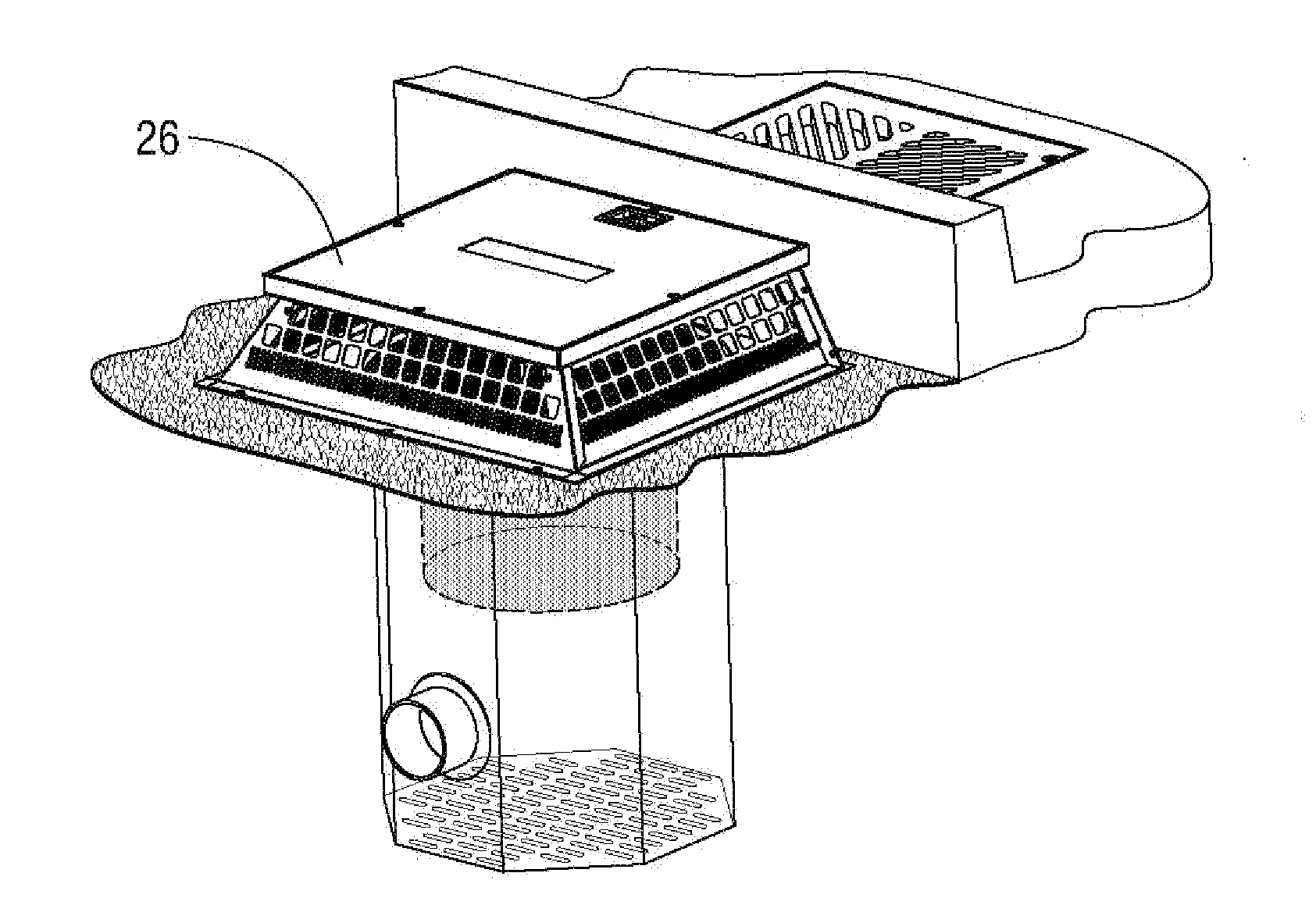
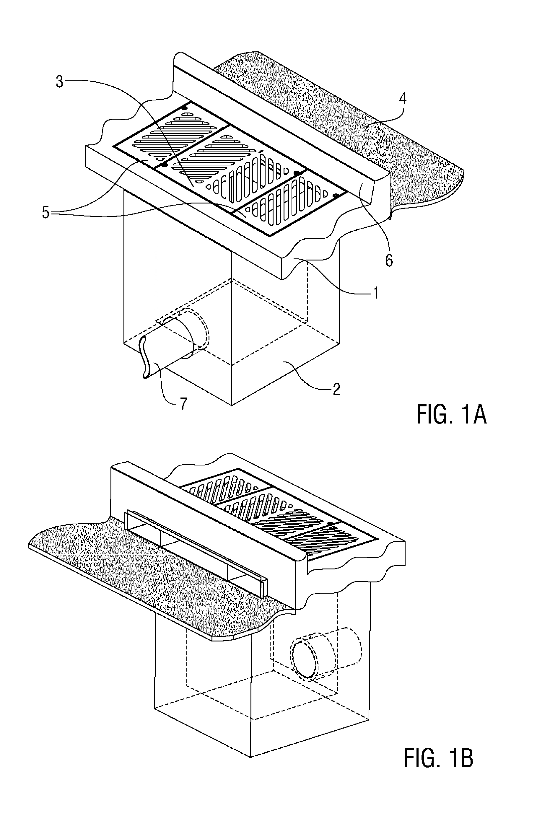
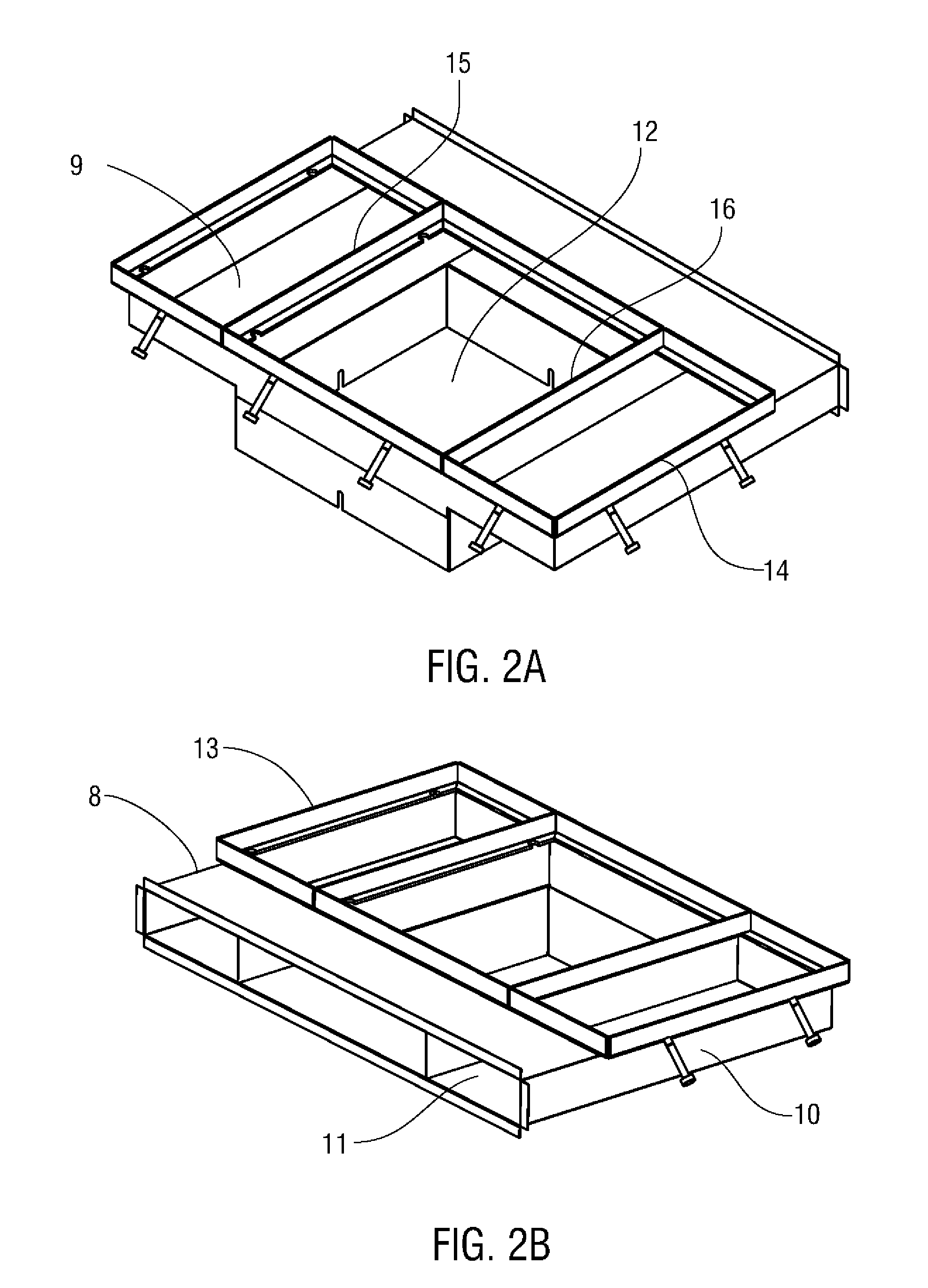
[0025]The present invention provides one or more components for a wide range of storm water management applications. These include but are not limited to include controlling and treating storm water flow in parking lot islands, median strips, and traffic islands, median strips, sidewalks, and...


PUM

PropertyMeasurementUnit
perimeteraaaaaaaaaa
heightaaaaaaaaaa
treatment areaaaaaaaaaaa

Abstract

The invention provides structures, methods, and assemblies for processing fluid entering a treatment area. The invention also provides methods, apparatuses, and additional structures that are useful for managing storm water flow and inhibiting the flow of pollutants, debris, and other contaminants into drainage systems. One or more flow diverter pans are installed at one or more inlets of a treatment area, such as a bioretention treatment area or a storm water retention and detention system. The apparatus comprises a structural framework that can include a pan placed adjacent to an inlet of the treatment area, and internal walls extending upward from the floor of the pan and at least partially framing a bypass opening adjacent to the floor. Inlet and outlet openings of the pan define a primary flow route for fluid passing through the pan and to the surface of the treatment area. Inlet and bypass openings of the pan comprise a secondary flow route for fluid passing through the tray.

Description

FIELD OF THE INVENTION[0001]The present invention relates to apparatuses and methods that are useful for treating or filtering storm water runoff, and more particularly to apparatuses and methods for use in conjunction with storm water treatment areas, such as bioretention treatment areas or storm water retention and detention assemblies, to manage storm water flow and inhibit the flow of pollutants, debris, and other contaminants into drainage systems.BACKGROUND OF THE INVENTION[0002]Many federal and state regulatory schemes require controlling storm water run-off and water quality, such as levels of pollutants on new developments of land. Before land development, an area will likely have included a variety of natural land features, such as sand dunes, grassy hills and wetlands. The natural land features absorb rainwater and infiltrate storm water runoff into the soil to replenish groundwater and streams. Following land development, however, the area might contain impervious surfac...

Claims


Application Information

Patent Timeline
Patent Type & Authority Applications(United States)
IPC IPC(8): E03F1/00
CPCE03F1/002E03F5/0401Y10T29/49826
Inventor ALLARD, DOUGLAS PAUL
Owner OLDCASTLE PRECAST
Why Eureka
Try Eureka