Additive layer manufacturing method

Inactive Publication Date: 2014-12-18
ROLLS ROYCE PLC
View PDF12 Cites 79 Cited by
  • Summary
  • Abstract
  • Description
  • Claims
  • Application Information

AI Technical Summary

Benefits of technology

The present invention provides an improved method for producing three-dimensional products using additive layer manufacturing (ALM) technology. The method involves focusing energy on a powder layer to fuse the area of the powder layer and form a cross-section of the product. The method also involves focusing energy on a support area of the powder layer to form a support pin that supports the downwardly facing surface of the product. The support pins can be cylindrical or elliptical in shape and can be formed in a spaced array or non-parallel to each other. The method can be used to manufacture components of gas turbine engines and the support pins can be removed to form the final component. The technical effects of the invention include improved accuracy and efficiency in the production of complex three-dimensional products.

Problems solved by technology

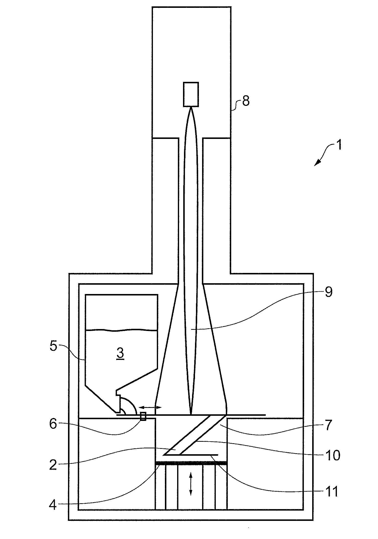
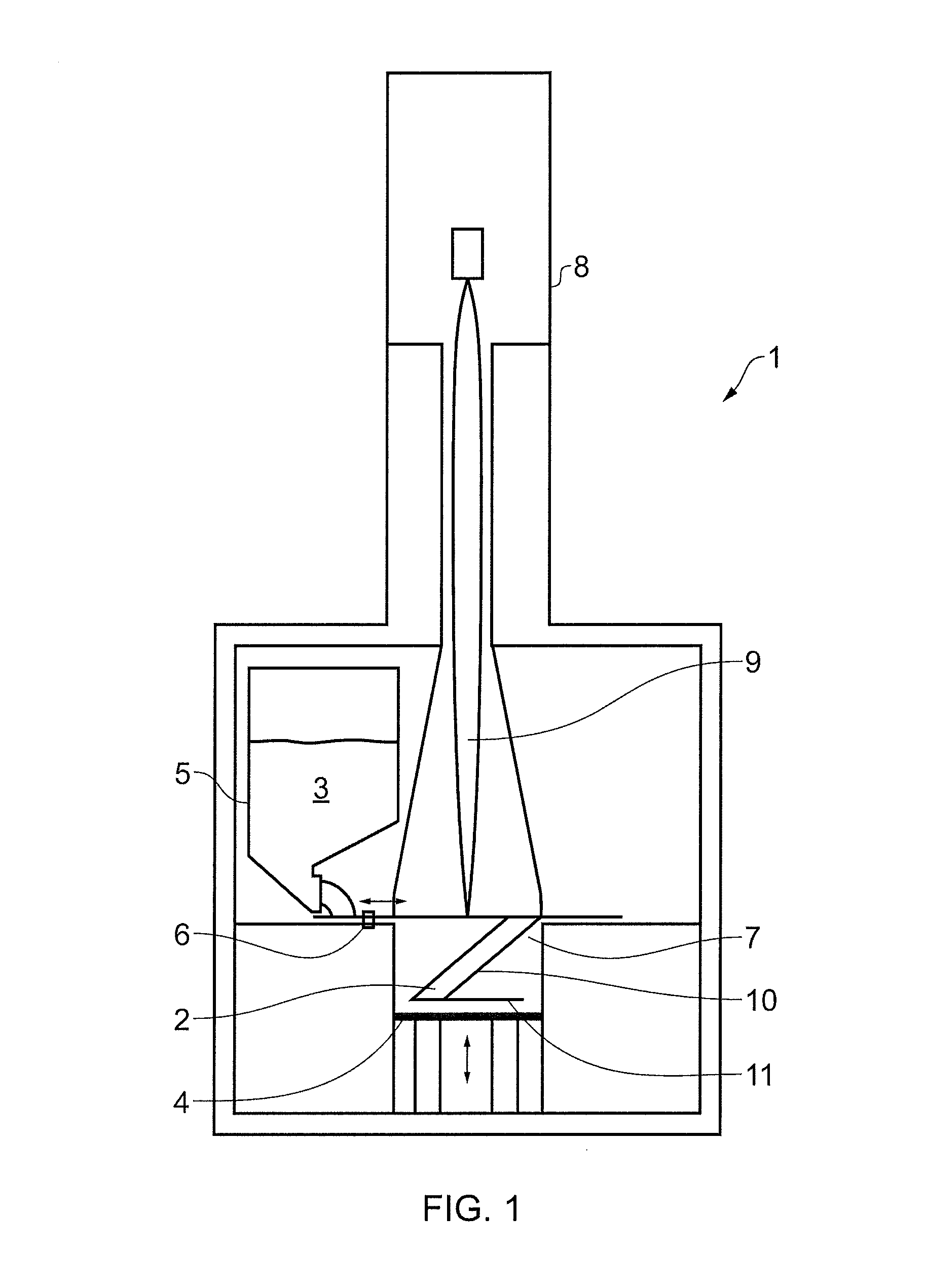
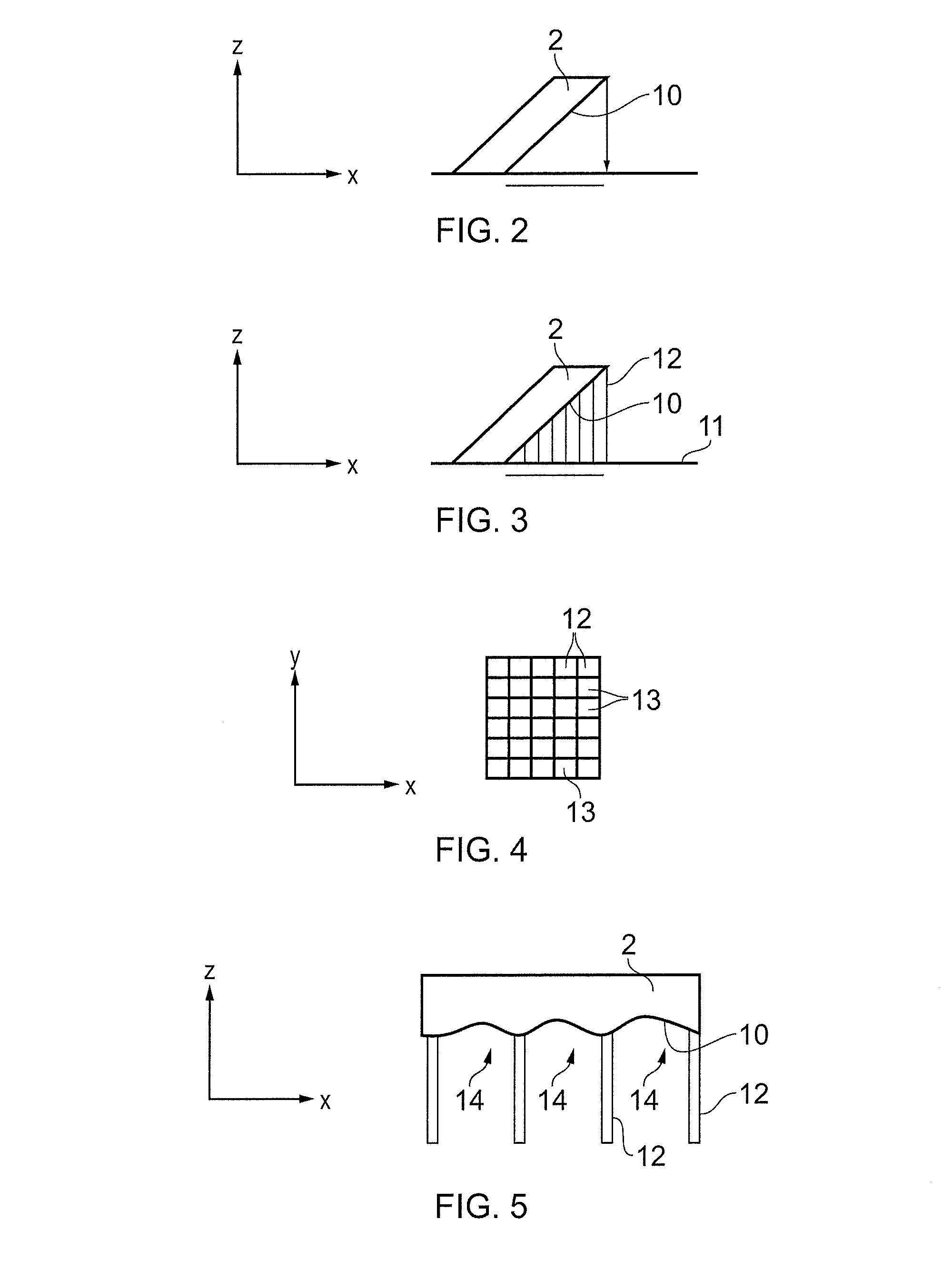
If no support is provided beneath downwardly facing surfaces 10 of the product 2 as it is formed, then localised overheating can occur during melting of the powder by the beam 9 which can result in poor surface finish to the product.
Powder feedstock used to manufacture component parts of gas turbine engines is typically very expensive, so this wastage increases the overall manufacturing cost.
It has often been found that the wafer supports 12 produced by prior art methods can be difficult to remove from some intricately shaped products during subsequent finishing processes.
Both reduce the manufacturing efficiency for the component
Distortion of the downwardly facing surface 10 represents another problem that can arise when utilising wafer supports 12.

Method used


Image

  • Additive layer manufacturing method
  • Additive layer manufacturing method
  • Additive layer manufacturing method

Examples


Embodiment Construction

[0047]Turning now to consider the drawings in more detail, the method of the present invention will now be described in detail, with particular reference to FIGS. 6 to 16.

[0048]The technical effect of the present invention can most easily be understood with regard to FIGS. 6 and 7 which show a product 20 which is manufactured by the method of the invention. The product 20 illustrated in FIGS. 6 and 7 is a metal product and is formed via an ALM method from metal powder.

[0049]As illustrated most clearly in FIG. 6, the product has a horizontally oriented lower surface 21 which is downwardly facing. FIG. 6 also shows the downwardly facing surface 21 being supported by a plurality of narrow and elongate support pins 22 which extend downwardly from the downwardly facing surface 21.

[0050]FIG. 7 shows the arrangement of the support pins 22 as viewed from below the product 20 and shows the support pins 22 arranged in a generally regular array across the downwardly facing surface 20. The pins...


PUM

PropertyMeasurementUnit
Diameteraaaaaaaaaa
Diameteraaaaaaaaaa
Areaaaaaaaaaaa

Abstract

An additive layer manufacturing method includes the steps of: a) laying down powder layer on powder bed, and b) focussing energy on an area of powder layer to fuse area of powder layer and thereby form a cross-section of the product; wherein steps a) and b) are repeated to form successive cross-sections of product, and wherein at least one of said steps b) involves focussing energy on an area of respective powder layer which is unsupported by a previously formed cross-section of product to thereby form a downwardly facing surface of product. Method is at least some of said successive steps b) involve focussing energy on a support area of respective powder layer, to fuse support area and thereby form successive cross-sections of a support pin within powder bed, support pin extending outwardly from downwardly facing surface of product when it is formed, so as to support downwardly facing surface.

Description

CROSS-REFERENCE TO RELATED APPLICATIONS[0001]This application is based upon and claims the benefit of priority from British Patent Application Number 1310762.8 filed 17 Jun. 2013, the entire contents of which are incorporated by reference.BACKGROUND OF THE INVENTION[0002]1. Field of the Disclosure[0003]The present invention relates to an additive layer manufacturing (ALM) method, and more particularly relates to an ALM for the production of a three-dimensional product via successive fusion of parts of a powder bed, said parts corresponding to successive cross-sections of the product.[0004]2. Description of the Related Art[0005]Additive layer manufacturing has become more widely used over recent years in order to produce three-dimensional products. Electron Beam Melting (EBM) is a particular type of ALM technique which is used to form fully dense metal products (such as component parts for gas turbine engines in the aerospace industry). The technique involves using an electron beam i...

Claims


Application Information

Patent Timeline
IPC IPC(8): B23K15/00
CPCB23K15/0006B23K15/0086B22F5/009B29C64/153B29C64/40Y02P10/25B22F10/28B22F10/73B22F10/47
Inventor WOOD, SCOTT DAVIDBLACKMORE, MICHAEL LEWISTODD, IAIN
Owner ROLLS ROYCE PLC
Why Eureka
Try Eureka