Fuel system control

a technology of fuel system and control panel, which is applied in the direction of machines/engines, mechanical equipment, transportation and packaging, etc., can solve the problems of insufficient reliability of fuel door detection, inability to reliably determine if sufficient depressurization has occurred, and insufficient temperature variation of fuel system to accurately infer fuel tank depressurization. accurate identification, reduced need for additional hardware for detecting depressurization, and improved reliability

Active Publication Date: 2014-12-25
FORD GLOBAL TECH LLC
View PDF5 Cites 25 Cited by
  • Summary
  • Abstract
  • Description
  • Claims
  • Application Information

AI Technical Summary

Benefits of technology

[0005]In one example, some of the above issues may be addressed by a method for a fuel system coupled in a hybrid vehicle. The method may comprise, during refueling conditions, directing fuel tank vapors to an engine intake manifold, and indicating depressurization of a fuel tank based on an output of a mass air flow sensor coupled to the intake manifold. In this way, depressurization may be reliably determined even if a fuel tank pressure sensor goes bad.
[0008]In this way, an auxiliary method is provided for verifying fuel tank depressurization during refueling. By diverting excess fuel tank pressure or vacuum to an engine intake, tank depressurization may be inferred based on flow of air or vapors from the sealed fuel tank to the engine intake. By using an existing MAF sensor to detect the flow, the need for additional hardware for detecting depressurization is reduced. By relying on the output of a fuel tank pressure sensor and a MAF sensor to detect depressurization, the reliability of the results is improved. In addition, depressurization can be accurately identified using the MAF sensor even when the fuel tank pressure sensor is degraded. By holding the fuel door locked until fuel tank depressurization is confirmed, the vehicle operator may be protected from fuel spray. In addition, evaporative hydrocarbon emissions (or leakage) is reduced.

Problems solved by technology

However, the inventors herein have recognized potential issues with such systems.
As one example, in hybrid vehicles have drastically reduced engine running times (such as PHEVs), fuel system temperatures may not vary enough to correctly infer fuel tank depressurization.
If the fuel system pressure sensor is degraded, the fuel tank temperature may not be reliably used to determine if sufficient depressurization has occurred.
If depressurization is not correctly determined, the fuel door may remain locked and the operator may not be able to refill the fuel tank.
Alternatively, the operator may get showered with fuel mist if the fuel door is opened prematurely.

Method used


Image

  • Fuel system control
  • Fuel system control
  • Fuel system control

Examples


Embodiment Construction

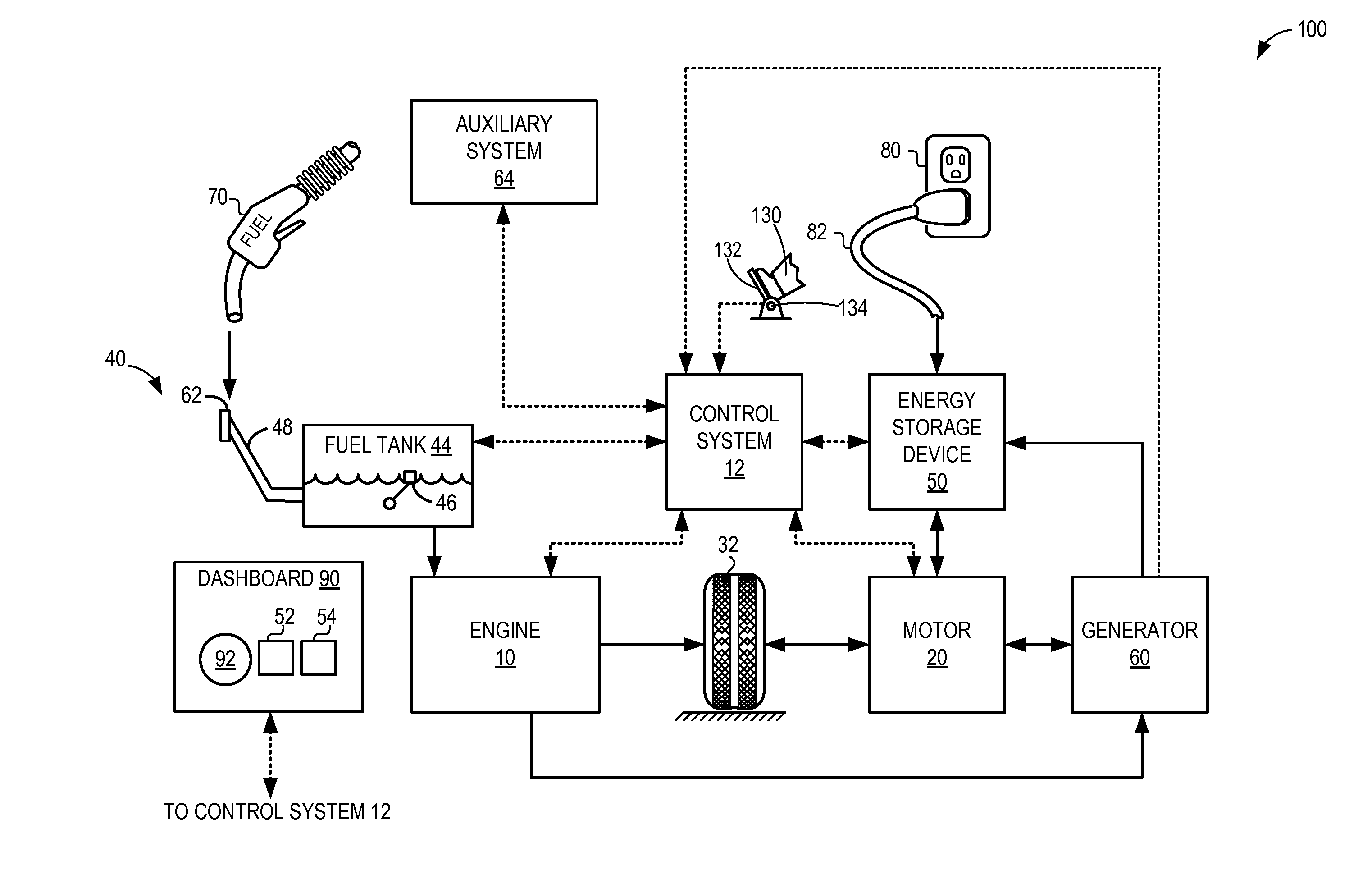
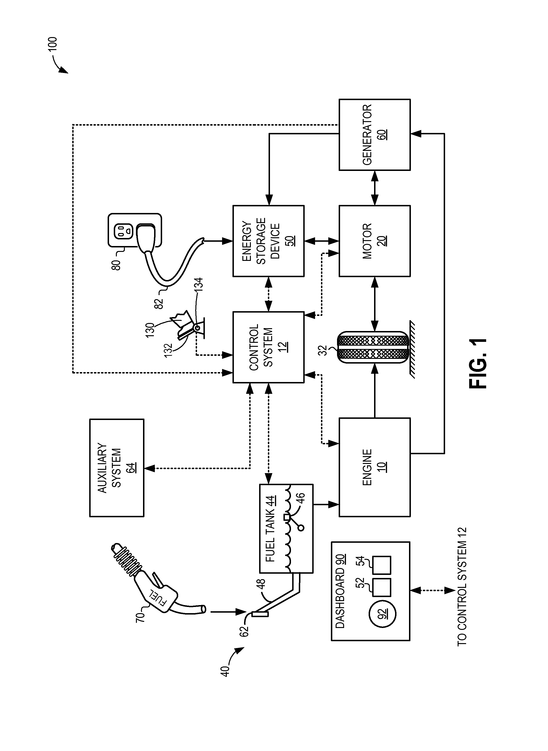
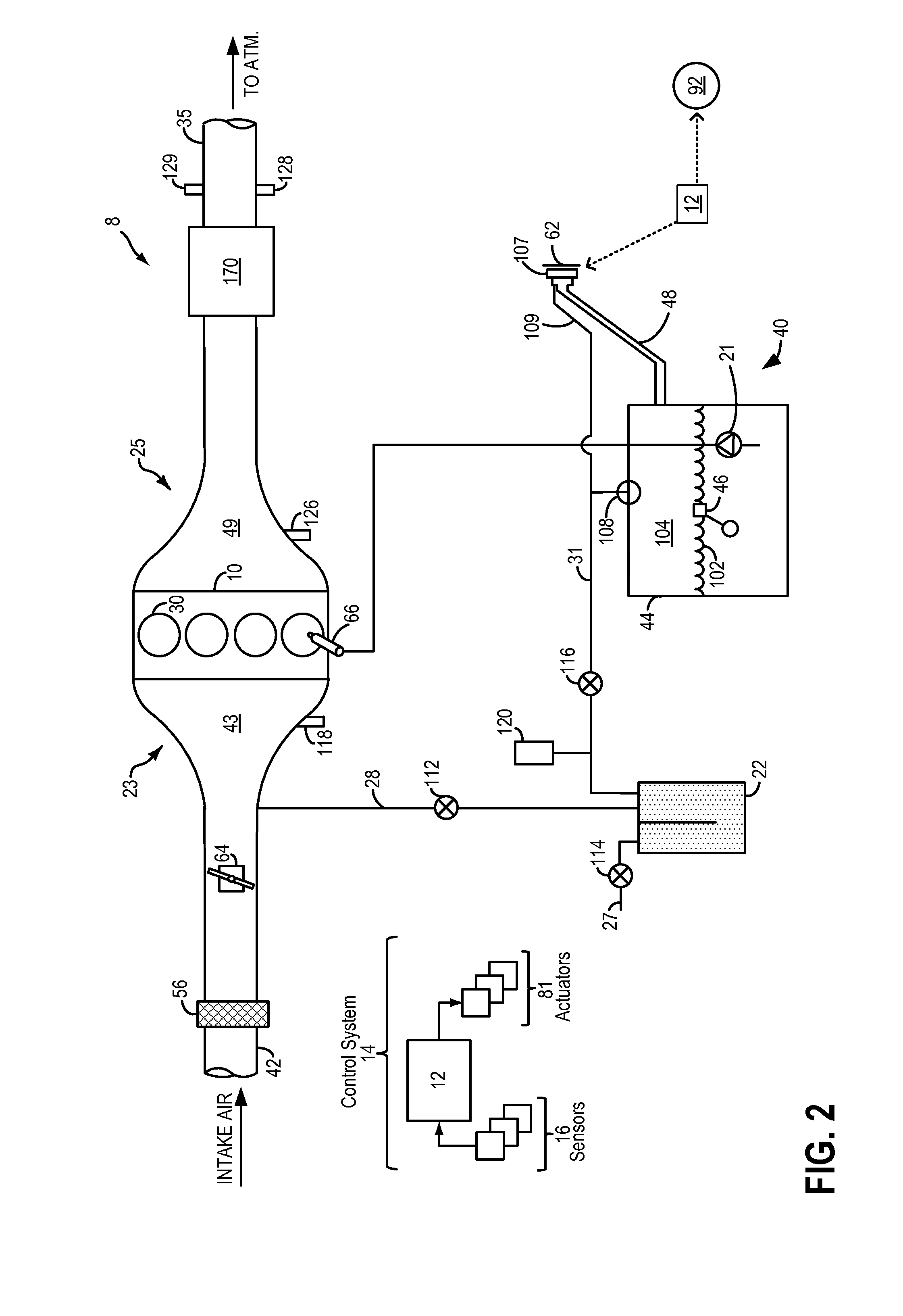
[0014]The following description relates to systems and methods for operating a hybrid electric vehicle, such as the plug-in hybrid electric vehicle of FIG. 1. In response to a refueling request from a vehicle operator, an engine fuel system (such as the fuel system of FIG. 2) may be sealed and excess fuel tank pressure / vacuum may be relieved in to an engine intake manifold. A controller may be configured to perform a routine, such as shown in FIG. 3, to infer fuel tank depressurization by sensing the flow of air or vapors from the fuel tank to the intake manifold at an intake MAF sensor. During the depressurization, a fuel door may be held locked. When the MAF sensor stops responding, fuel tank depressurization may be determined to be complete and the fuel door may be unlocked enabling the vehicle operator to refill the fuel tank. An example refueling operation is shown at FIG. 4. In this way, fuel tank over-pressure conditions may be reliably inferred even if a fuel tank pressure s...


PUM


Abstract

Methods and systems are provided for accurately confirming fuel tank depressurization before unlocking a fuel door to enable refueling. Following a refueling request, a fuel system may be sealed from the atmosphere while one or more fuel system valves are adjusted to divert fuel tank pressure or vacuum to an engine intake. Depressurization may be inferred based on the presence of air or vapor flow into the intake as sensed by a manifold airflow sensor.

Description

FIELD[0001]The present description relates to systems and methods for inferring fuel system depressurization in a hybrid vehicle.BACKGROUND AND SUMMARY[0002]Hybrid vehicle fuel systems may include a sealed fuel tank configured to withstand high fuel tank pressure and vacuum levels. Fuel tank pressure or vacuum levels may build up due to engine operating conditions as well as the generation of diurnal vapors over vehicle drive cycles. During refueling of a fuel tank, a fuel door may be maintained locked until sufficient depressurization has occurred to disable refueling of a pressurized fuel tank. A fuel tank pressure sensor may be used to determine if there is excess pressure or vacuum build-up in the fuel tank, and if depressurization is required. During the depressurization, fuel tank vapors may be released into and stored in a fuel vapor canister packed with an adsorbent by opening a valve coupled between the fuel tank and the canister. At a later time, when the engine is in oper...

Claims


Application Information

Patent Timeline
Patent Type & Authority Applications(United States)
IPC IPC(8): B60K15/035B60K6/22F02M25/08
CPCY10S903/904B60K2015/03561B60K6/22F02M25/0836B60K15/035B60Y2200/92Y10T137/0396
Inventor YANG, DENNIS SEUNG-MANDUDAR, AED M.
Owner FORD GLOBAL TECH LLC
Why Eureka
Try Eureka