Chromatographic medium

Active Publication Date: 2014-12-25
DAICEL CHEM IND LTD
View PDF6 Cites 2 Cited by
  • Summary
  • Abstract
  • Description
  • Claims
  • Application Information

AI Technical Summary

Benefits of technology

[0031]In the chromatographic medium of the present invention, the filling agent layer comes into contact with the aforementioned separating agent layer via a plane that intersects the direction of development of the aforementioned target substances in the aforementioned chromatographic medium and is positioned on the upstream side in the aforementioned direction of development. As a result, when the aforementioned target substances are developed after being fixed in the part that contains this filling agent layer, the target substances are temporarily concentrated at the separating agent layer side of the boundary between the filling agent layer and the separating agent layer due to the filling agent layer and separating agent layer exhibiting dif

Problems solved by technology

When used in separating agent layers for TLC plates, such separating agents that contain aromatic rings are, in some cases, unable to detect components to be detected when irradiating with ultraviolet rays or carrying out coloration treatment using a coloring reagent.
In addition, because the speed of migration of a spot generally varies in each separating agent

Method used


Image

  • Chromatographic medium
  • Chromatographic medium
  • Chromatographic medium

Examples


example 1

[0183]Firstly, a first slurry was prepared by adding 3.00 g of a Chiralpak IA (registered trademark) manufactured by Daicel Corporation (“IA Filler”), 0.45 g of gypsum, 3.00 g of an aqueous solution containing 2% of 1110 grade CMC (carboxymethyl cellulose, manufactured by Daicel Corporation) and 0.45 g of an aqueous solution containing 20% of Snowtex C (manufactured by Nissan Chemical Industries, Ltd.) to a mixed solution containing 0.30 g of water and 1.20 g of ethanol, and then stirring vigorously while irradiating with ultrasonic waves.

[0184]In addition, a second slurry was prepared by adding 2.00 g of silica gel (IR-60-5 / 20-U, liquid chromatography grade manufactured by Daiso), 0.10 g of gypsum, 3.00 g of an aqueous solution containing 2% of 1110 grade CMC (carboxymethyl cellulose, manufactured by Daicel Corporation), 0.02 g of a manganese-containing zinc silicate, and 0.30 g of an aqueous solution containing 20% of Snowtex C (manufactured by Nissan Chemical Industries, Ltd.) to...

example 2

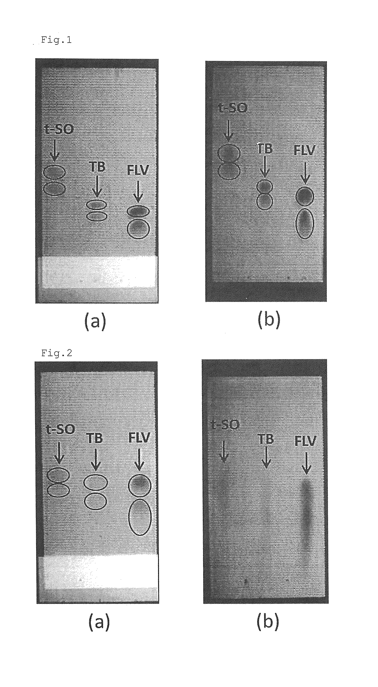
[0194]Optical isomers of the trans-stilbene oxide, Tröger's base and flavanone in the sample were developed in the direction of development of the TLC plate 1 using the same procedure as that used in Example 2, except that a TLC plate 2, which was prepared using the same raw materials and procedure as those used for TLC plate 1 prepared in Example 1, was used and methanol was used as the developing solution. Next, the Rf value, k′ value and α value for each spot was determined in the same way as in Example 1 from the position at which the sample was applied on the permeation layer, the position reached by the developing solution and the position of the center of the spot. The results for these optical isomers are shown in Table 2.


PUM

PropertyMeasurementUnit
Diameteraaaaaaaaaa
Diameteraaaaaaaaaa
Lengthaaaaaaaaaa

Abstract

Provided is a chromatographic medium capable of separating and detecting target substances without the use of other components. A chromatographic medium having a separating agent layer, which is used to separate target substances, a filling agent layer, which is used to fix the target substances before the target substances are separated, and a permeation layer, which is used to enable permeation of the target substances separated by the separating agent layer, wherein the filling agent layer comes into contact with the separating agent layer via a plane that intersects the direction of development of the target substances in the chromatographic medium and is positioned on the upstream side in the direction of development, the separating agent layer exhibits separability of the target substances and exhibits optical responsiveness to ultraviolet rays, and the permeation layer exhibits optical responsiveness that are different from those of the target substances and the separating agent layer.

Description

TECHNICAL FIELD[0001]The present invention relates to a chromatographic medium at least having two layers having different optical responsiveness to ultraviolet rays, and further having another layer.BACKGROUND ART[0002]Thin layer chromatography (hereinafter also referred to as “TLC”) is known as a method for separating and detecting specific components in a mixture. When separating components by means of TLC, detection is achieved by subjecting spots, which are obtained by developing a sample, to irradiation with ultraviolet rays or to coloration treatment using a coloring reagent on the basis of differences in optical responsiveness of, for example, a separating agent layer and the components being detected.[0003]Meanwhile, separating agents that contain polysaccharide derivatives such as phenyl esters of polysaccharides are known as separating agents for optical isomers. When used in separating agent layers for TLC plates, such separating agents that contain aromatic rings are, i...

Claims


Application Information

Patent Timeline
IPC IPC(8): G01N30/92B01J20/291B01D15/08
CPCG01N30/92B01D15/08B01J2220/46B01J2220/54B01J20/291G01N30/93G01N2030/8877G01N2030/945
Inventor MINODA, TOSHIHARUIKEDA, ISAMU
Owner DAICEL CHEM IND LTD
Why Eureka
Try Eureka