Outdoor luminaire

a technology for outdoor lighting and luminaires, which is applied in the direction of luminescent compositions, semiconductor devices of light sources, lighting and heating apparatus, etc., can solve the problems of undesirable replacement and the expected lowering of the quantum efficiency of phosphor, and achieve the effect of brighter lighting and higher visual perception

Inactive Publication Date: 2014-12-25
SHIN ETSU CHEM IND CO LTD
View PDF7 Cites 7 Cited by
  • Summary
  • Abstract
  • Description
  • Claims
  • Application Information

AI Technical Summary

Benefits of technology

[0023]The outdoor luminaire of the invention produces illumination affording brighter lighting, higher visual perception and brightness over a broader range under scotopic and mesopic vision conditions.

Problems solved by technology

However, such replacement is undesirable for lighting applications because a lowering of quantum efficiency of the phosphor is expected.

Method used


Image

  • Outdoor luminaire
  • Outdoor luminaire
  • Outdoor luminaire

Examples


example 1

[0046]A powder mixture, 1,000 g, was obtained by mixing lutetium oxide (Lu2O3) powder of 99.9% purity having an average particle size of 1.0 μm, aluminum oxide (Al2O3) powder of 99.0% purity having an average particle size of 0.5 μm, and cerium oxide (CeO2) powder of 99.9% purity having an average particle size of 0.2 μm in a molar ratio Lu:Al:Ce of 2.97:5.0:0.03. Barium fluoride, 200 g, as flux was added to the powder mixture, which was thoroughly mixed. The mixture was placed in an alumina crucible and heat treated in argon gas at 1,400° C. for 10 hours. The fired product was disintegrated on a ball mill, washed with about 0.5 mol / L hydrochloric acid and then with deionized water. Subsequent solid / liquid separation and drying yielded Lu3Al5O12:Ce3+ phosphor particles (Ce-activation rate relative to Lu is 1 mol %) having an average particle size of 20 μm.

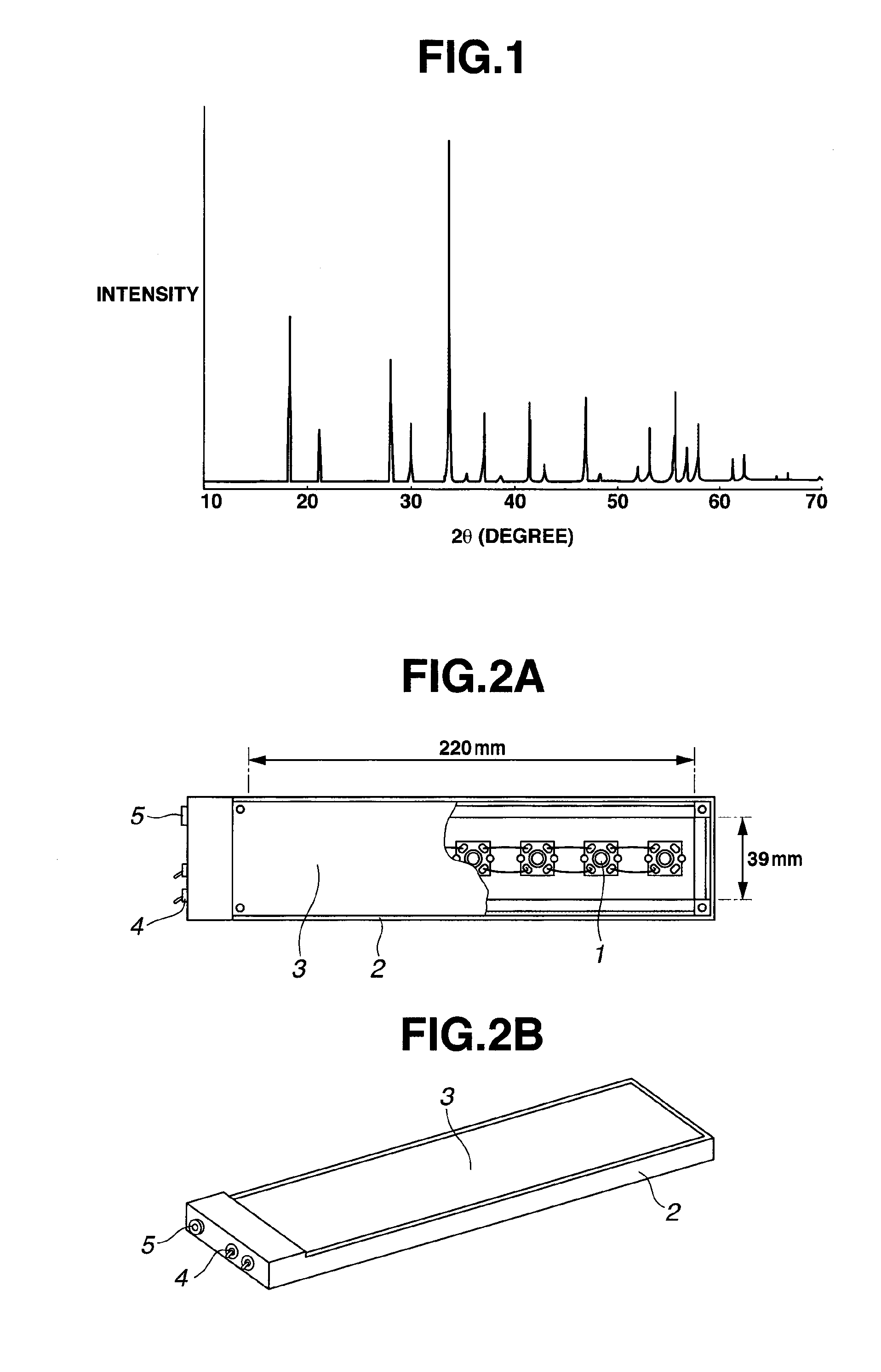
[0047]The result of XRD analysis of the phosphor particles is shown in FIG. 1. The diffraction pattern of main phase of the phosp...

example 2

[0051]A powder mixture, 1,000 g, was obtained by mixing yttrium oxide (Y2O3) powder of 99.9% purity having an average particle size of 1.0 μm, aluminum oxide (Al2O3) powder of 99.0% purity having an average particle size of 0.5 μm, and cerium oxide (CeO2) powder of 99.9% purity having an average particle size of 0.2 μm in a molar ratio Y:Al:Ce of 2.94:5.0:0.06. Barium fluoride, 200 g, as flux was added to the powder mixture, which was thoroughly mixed. The mixture was placed in an alumina crucible and heat treated in argon gas at 1,400° C. for 10 hours. The fired product was disintegrated on a ball mill, washed with about 0.5 mol / L hydrochloric acid and then with deionized water. Subsequent solid / liquid separation and drying yielded Y3Al5O12:Ce3+ phosphor particles having an average particle size of 20 μm.

[0052]An LED package with a phosphor layer was manufactured as in Example 1 except that the Lu3Al5O12:Ce3+ phosphor particles in Example 1 and the Y3Al5O12:Ce3+ phosphor particles ...

example 3

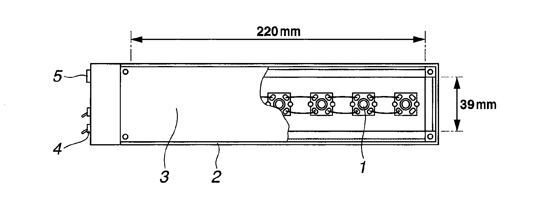
[0054]Seven blue LED packages (XLamp LX-E Royal Blue by Cree Inc.) were arranged in an aluminum chassis and connected in series as in Example 1. The Lu3Al5O12:Ce3+ phosphor particles in Example 1 were kneaded in polycarbonate in a phosphor concentration of 5 wt %, and the resulting PC compound was molded into a PC plate of 2 mm thick. This PC plate as the phosphor layer was attached at a position spaced 25 mm apart from the emissive surface of the blue LED packages. An LED luminaire of remote phosphor type was fabricated as shown in FIG. 2, wherein the protective cover 3 also serves as a phosphor layer.

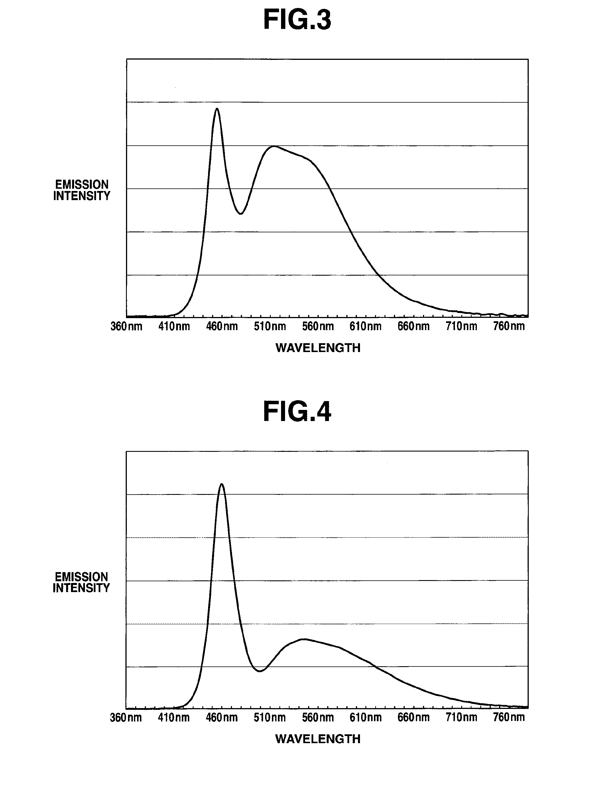
[0055]The spectrum of illuminating light of the LED luminaire was measured as in Example 1. The intensity ratio S1 / S2 was 1.067.


PUM


Abstract

An outdoor luminaire comprising a blue LED chip having a maximum peak at a wavelength of 420-480 nm and a phosphor layer disposed forward of the LED chip in its emission direction is provided. The phosphor layer comprises a phosphor of the formula: Lu3Al5O12:Ce3+ which is activated with up to 1 mol % of Ce relative to Lu, the phosphor being dispersed in a resin. In scotopic and mesopic vision conditions, the luminaire produces illumination affording brighter lighting, higher visual perception and brightness over a broader area.

Description

CROSS-REFERENCE TO RELATED APPLICATION[0001]This non-provisional application claims priority under 35 U.S.C. §119(a) on Patent Application No. 2013-132462 filed in Japan on Jun. 25, 2013, the entire contents of which are hereby incorporated by reference.TECHNICAL FIELD[0002]This invention relates to an outdoor luminaire suitable for installation in those areas that are dim or dark at night or where least lamps are available, for example, pathways, roadways, plazas, residential areas, and tunnels.BACKGROUND ART[0003]In modern cities, most areas are brightly illuminated even at night by many light sources including automobile headlights and store illuminations. On the other hand, most areas in suburbs and provincial districts are dark at night. Thus such areas as pathways, roadways, parks, and tunnels are provided with streetlights and outdoor luminaires for the safety and security purposes.[0004]However, when high-intensity luminaires are installed in suburbs and provincial districts...

Claims


Application Information

Patent Timeline
Patent Type & Authority Applications(United States)
IPC IPC(8): H01L33/50F21K99/00
CPCF21K9/50H01L33/50C09K11/7774F21K9/60C09K11/7715F21K9/64F21Y2115/10H01L33/502
Inventor TSUMORI, TOSHIHIROTSUKATANI, TOSHIHIKOWATAYA, KAZUHIROMINOWA, TAKEHISA
Owner SHIN ETSU CHEM IND CO LTD
Why Eureka
Try Eureka