Rigid stiffener-reinforced flexible neural probes, and methods of fabrication using wicking channel-distributed adhesives and tissue insertion and extraction

a flexible, rigid technology, applied in the field of thin film microprobes and fabrication methods, can solve the problems of localized tissue damage at the probe's tip, stability and longevity of stimulation and recording functions, and the stiffness of silicon-based neural probes, etc., to achieve attachment, and precise positioning. , the effect of accurate and repeatable alignmen

Active Publication Date: 2014-12-25
LAWRENCE LIVERMORE NAT SECURITY LLC
View PDF9 Cites 14 Cited by
  • Summary
  • Abstract
  • Description
  • Claims
  • Application Information

AI Technical Summary

Benefits of technology

[0021]In many microsystems applications, it is critically important to precisely and accurately align and attach two substrates to each other using permanent or temporary adhesives. At the millimeter and micron scales, the accuracy of attachment is largely dependent on the amount and coverage of adhesive dispensed. Excess adhesive can overflow from the bond interface and damage the substrates, while inadequate adhesive creates a non-uniform bond. The present invention provides a method for consistently and uniformly dispensing adhesive on a substrate (e.g. stiffener), to attach it to another substrate (e.g. flexible probe) with precision and accuracy in all spatial dimensions (length, width, height).
[0022]In particular, this invention describes the use of a wicking channel to use capillary force to distribute a precise amount of adhesive along the length of the stiffener substrate prior to neural implant assembly. First, single or multiple channels (e.g. inter-connected channels) are created in a pattern that covers the areas that need to be attached. Second, a controlled amount of adhesive is dispensed into the channel or channels, which wicks along the channel using capillary forces to evenly coat and fill the channel. Alternately, the adhesive may be dispensed into a containment reservoir fluidically connected to the channel or channels. Finally, the two substrates (e.g. stiffener and flexible probe) are aligned and attached using a tool such as a flip-chip bonder which allows precise positioning in the lateral dimensions. The adhesive may be cured using a combination of temperature, pressure, light, and / or time. A stiffener design having wicking channels allows for uniform distribution of the PEG adhesive along the length of the probe. Flip-chip bonding, a common tool used in microelectronics packaging, enables accurate and repeatable alignment and attachment of the probe to the stiffener. The probe and stiffener are surgically implanted together, then the PEG is allowed to dissolve so that the stiffener can be extracted leaving the probe in place.
[0023]There are multiple advantages to the assembly methods and wicking-channel stiffener designs described in the embodiments of the present invention. Dispensed adhesive can be easily controlled. A pneumatic dispenser can precisely and repeatedly dispense the necessary amount of material for wicking, eliminating the chance of adhesive overflow. The reservoir and channel shapes can be optimized for uniform and controlled delivery of adhesive. Many types of adhesive with an appropriate viscosity can be applied into the reservoir of the stiffener and be wicked successfully. Adhesives of different bonding strengths can be tested. Bio-dissolvable adhesive can be used, which allows the stiffener to be removed from the tissue after the adhesive has dissolved. This technique is ideal for long-term implantation. In one embodiment of a temporary reversible adhesive, polyethylene glycol (PEG) is used, wherein the repeatable melting and solidification of the material is exploited to facilitate the assembly process using the wicking stiffener. First, micro-pellets of PEG are generated by melting some of the material on a surface on which the PEG exhibits hydrophobic behavior. Then the material is drawn or spread to create separate droplets of a desired size. The droplets are cooled and solidify into pellets. Pellets of the desired size (volume) can then be picked and placed onto the reservoir or channel on the tab portion of a wicking stiffener. After the pellet is satisfactorily placed, the stiffener is placed on a hot plate, where the PEG melts and wicks into the channel. The stiffener is cooled when wicking is complete, and the PEG solidified again. The stiffener can then be easily aligned to the probe without the risk of wet adhesive transferring to other surfaces in the process. Once aligned and placed, the assembly is heated again to distribute the PEG, and finally cooled to complete the assembly.
[0024]In this manner, microelectrode arrays for neural interface devices that are made of biocompatible thin-film polymer are expected to have extended functional lifetime because the flexible material may minimize adverse tissue response caused by micromotion.

Problems solved by technology

The stiffness of silicon-based neural probes, however, can have several limitations.
After insertion and implantation, any movement at the probe's end can cause localized tissue damage at the probe's tip due to the probe's stiffness.
Thus, a major challenge for implanted silicon-based neural probes in particular is stability and longevity of the stimulation and recording functions.
Though flexibility is advantageous for chronic implantation and use, flexible neural implants alone are often not stiff enough to penetrate neural tissue during surgical implantation.
This typically results in increased tissue damage.
This method has several limitations, in addition to those listed under the first method of the silicon only stiffener.
For example, hand-gluing the wire and probe tip together is a difficult and time-intensive technique.
Superglue is difficult to control and, if comes in contact with electrodes, will damage the device.
Moreover, once attached, the stiffening wire is permanently attached and cannot be removed from the body or the device.
However, methods such as these that permanently modify the geometry of the final implanted device may compromise some of the desirable features of the flexible probe.
However, typical biodegradable materials have Young's moduli orders of magnitude smaller than that of silicon and would consequently require larger thickness to achieve the same stiffness.
Adequately coating the probe can result in a more rounded or blunt tip, making insertion more difficult.
Also, since dissolvable coatings are exposed, there is a risk of them dissolving immediately upon contact, or even close proximity, with the tissue.
This method has several limitations as well.
When coating entire probe tip, film forms over the electrodes, possibly making the device unusable.
Finally, coating the probe leads to rounding of the tip, making insertion more difficult and destructive to tissue.
However, the achievable range of stiffness is still limited, so they may not be able to provide very high stiffness equivalent to silicon or tungsten wires.

Method used


Image

  • Rigid stiffener-reinforced flexible neural probes, and methods of fabrication using wicking channel-distributed adhesives and tissue insertion and extraction
  • Rigid stiffener-reinforced flexible neural probes, and methods of fabrication using wicking channel-distributed adhesives and tissue insertion and extraction
  • Rigid stiffener-reinforced flexible neural probes, and methods of fabrication using wicking channel-distributed adhesives and tissue insertion and extraction

Examples


example case

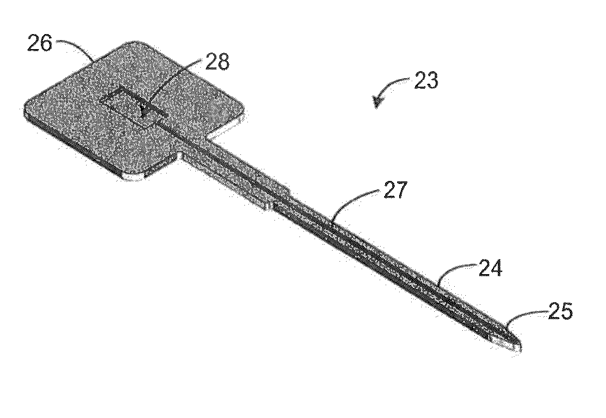
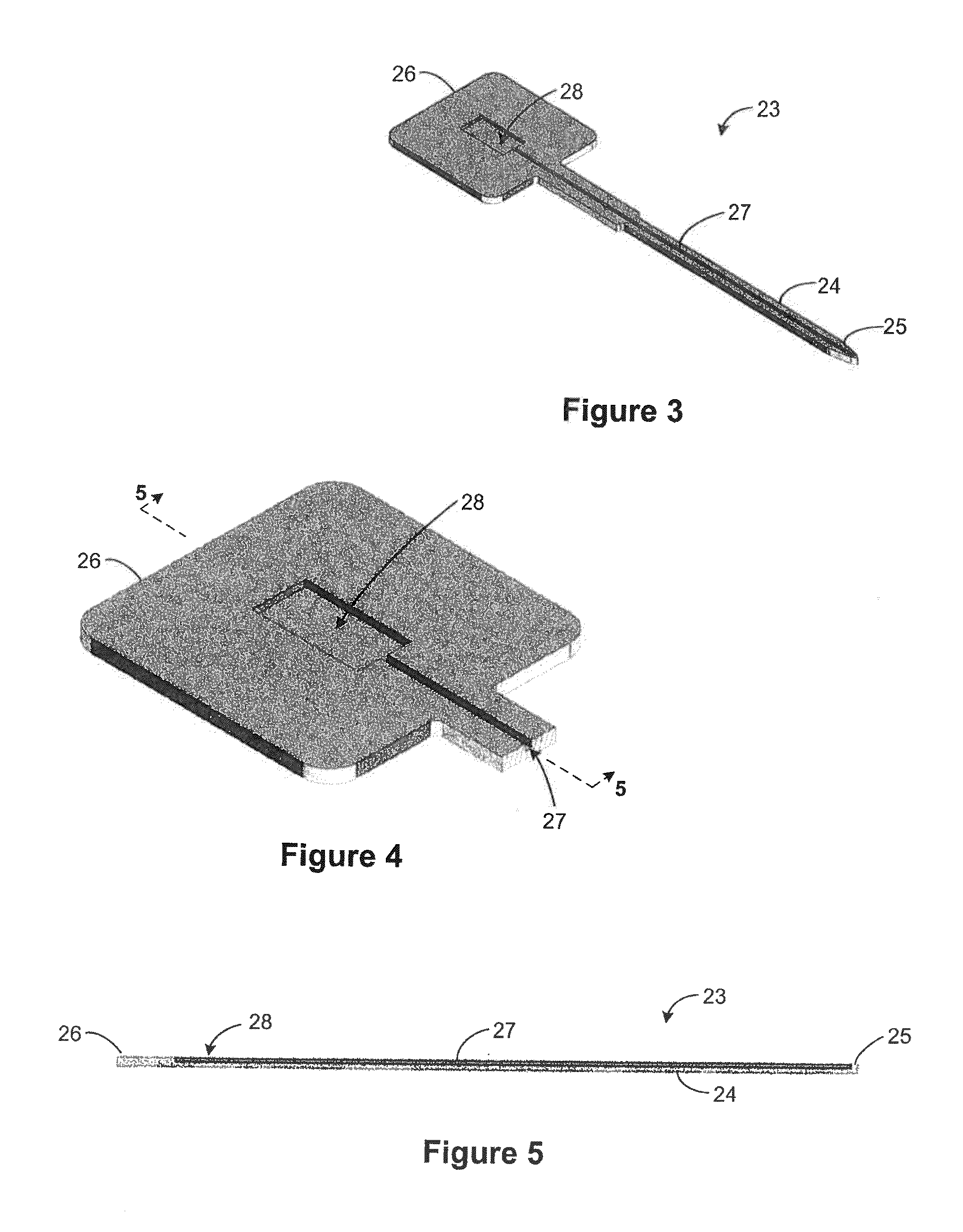
[0073]Assembly of Stiffener to Probe

[0074]An example method of assembly of a thin-film polymer probe to a silicon stiffener is next described:

[0075]A pellet of polyethylene glycol (PEG) of molecular weight 10,000 g / mol is first placed into a reservoir cavity at the tab section of the stiffener. The stiffener is then heated to 65° C. so that the PEG melts and wicks into the channel by capillary action. It is then cooled to room temperature to solidify. A flip chip bonder may be used next by placing the stiffener upside down on the base stage of the flip chip bonder. The stiffener is then picked up with the tool head. The elongated probe is positioned upside down on the base stage, i.e. the assembly base. Using the flip chip bonder, align the stiffener and the probe and then lower the stiffener and place it onto the probe. The base stage of the flip chip bonder should have a heating element to apply heat to the substrate. After placing the stiffener, the assembly is heated once again ...


PUM

PropertyMeasurementUnit
distanceaaaaaaaaaa
speedaaaaaaaaaa
thickaaaaaaaaaa

Abstract

A stiffener-reinforced microelectrode array probe and fabrication method using wicking channel-distributed adhesives which temporarily adheres a flexible device onto a rigid stiffener for insertion and extraction. Assembly is by dispensing a liquid adhesive into a narrow open groove wicking channel formed on the stiffener so that the adhesive is wicked along and tills the channel by capillary action, and adhering the adhesive-filled bonding side of the elongated section of the rigid substrate to a flexible device.

Description

II. CLAIM OF PRIORITY IN PROVISIONAL APPLICATION[0001]This patent document claims the benefit and priority of U.S. Provisional Application No. 61 / 594,774, filed on Feb. 3, 2012, hereby incorporated by reference.I. FEDERALLY SPONSORED RESEARCH OR DEVELOPMENT[0002]The United States Government has rights in this invention pursuant to Contract No. DE-AC52-07NA27344 between the United States Department of Energy and Lawrence Livermore National Security, LLC for the operation of Lawrence Livermore National Laboratory.III. FIELD OF THE INVENTION[0003]The present invention relates to the field of thin film microprobes and fabrication methods, and more particularly to flexible microelectrode array probes having rigid stiffeners permanently or temporarily adhered using wicking channel-distributed adhesives, to provide structural reinforcement to resist bending and buckling, especially during insertion.IV. BACKGROUND OF THE INVENTION[0004]Micro-electrode neural probes are essential tools in ne...

Claims


Application Information

Patent Timeline
Patent Type & Authority Applications(United States)
IPC IPC(8): A61B5/04B32B37/12A61B19/00A61N1/05
CPCA61B5/04001A61B19/201B32B37/1284A61N1/05A61N1/0534A61N1/0551A61B2562/125A61B90/11Y10T156/10Y10T428/24612A61B5/24
Inventor SHAH, KEDAR G.GEORGE, DIANEPANNU, SATINDERPALL G.FELIX, SARAH
Owner LAWRENCE LIVERMORE NAT SECURITY LLC
Why Eureka
Try Eureka