Drill rig and methods of manufacture and use of same

a technology of drilling rigs and rigs, which is applied in the direction of machines/engines, insulation, borehole/well accessories, etc., can solve the problems of negative affecting the efficiency of the loop field, and achieve the effect of high efficiency

Active Publication Date: 2015-01-01
ADELSBACH SCOTT
View PDF3 Cites 3 Cited by
  • Summary
  • Abstract
  • Description
  • Claims
  • Application Information

AI Technical Summary

Benefits of technology

[0006]It is one object of the invention to provide a novel drill rig that can be used to the insta...

Problems solved by technology

The gravel, concrete and asphalt over such loop fields also transfers colder temperatures from the outsid...

Method used


Image

  • Drill rig and methods of manufacture and use of same
  • Drill rig and methods of manufacture and use of same
  • Drill rig and methods of manufacture and use of same

Examples


Embodiment Construction

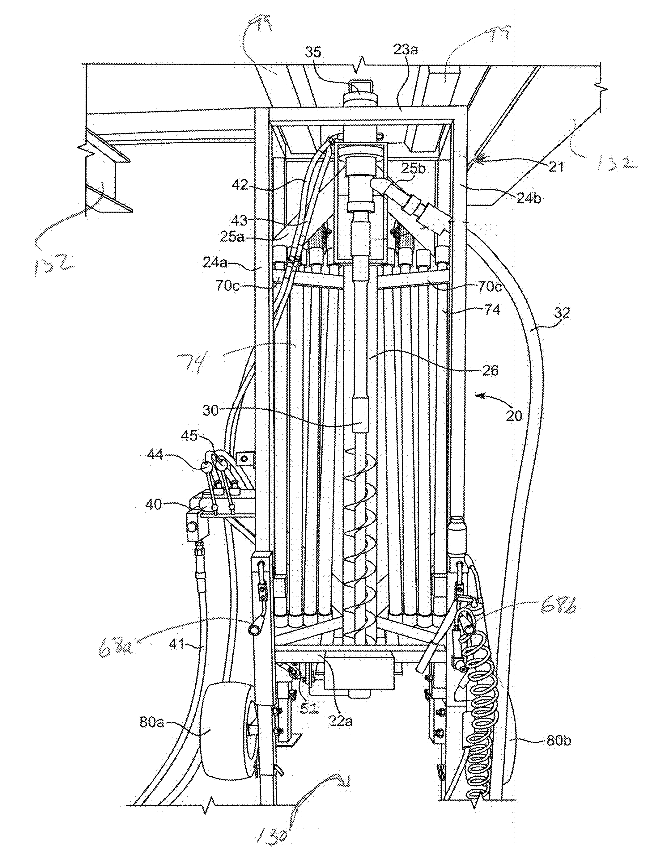
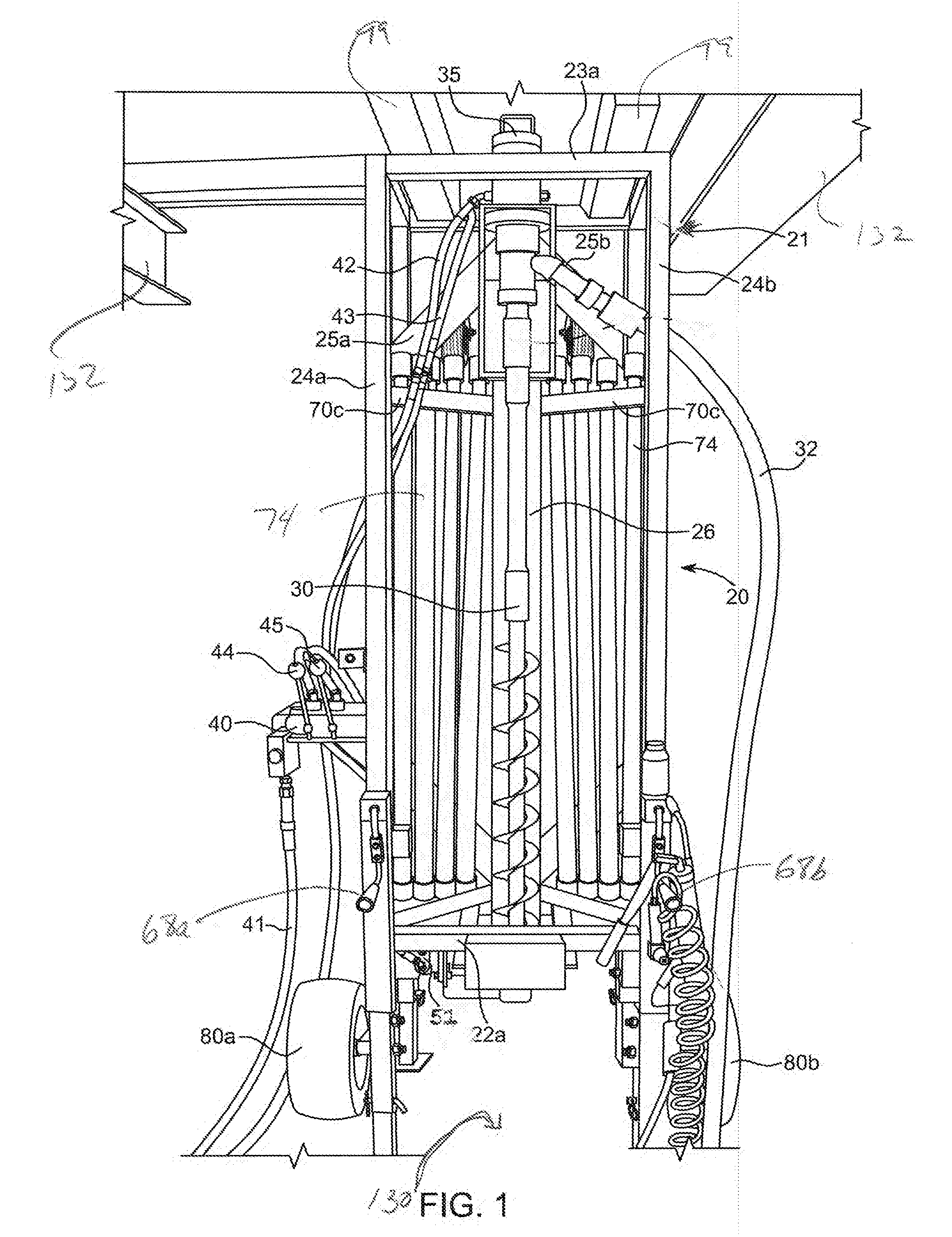
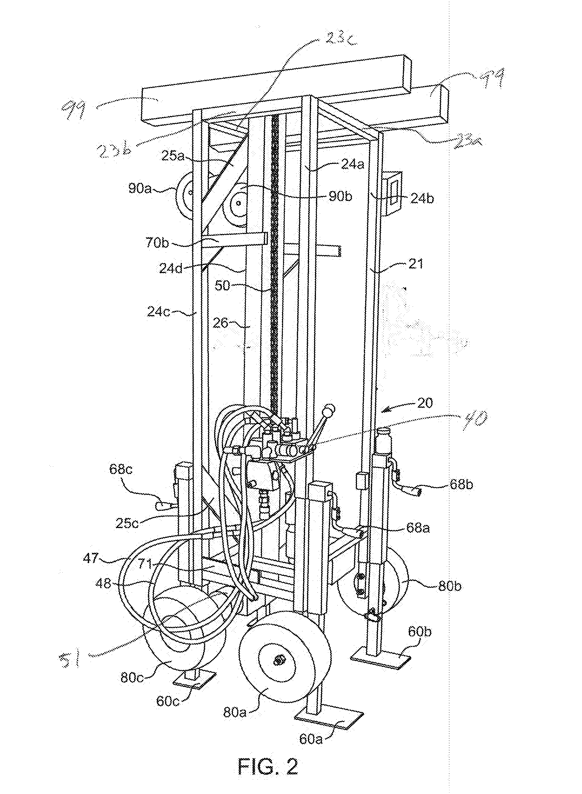
[0039]FIGS. 1-7 illustrate an embodiment of an improved, lightweight portable drill rig 20 in accordance with the invention. The rig 20 generally includes a frame 21, mast 26, drill bit 30, drill motor 35, hydraulic power control assembly 40, drive chain 50, drive chain motor 51, foot pads 60, pipe racks 70, bottom wheels 80, and peripheral wheels 90. The drill rig of the invention is designed to be lightweight and compact so that it can be maneuvered into basements and crawl spaces of existing buildings (including residential buildings) and down a standard sized building stair cases. The compact, lightweight design of the drill rig 20 allows it to be rolled down a staircase, dropped through a basement window, or lowered in unframed new construction onto the lowest floor of an existing building or new construction in order to drill a vertical loop geothermal loop field underneath such a structure. To enhance its portability and maneuverability, the entire rig 20 preferably weighs le...


PUM


Abstract

The present invention provides an improved drill rig for drilling vertical loop field for geothermal heating/air conditioning units, methods of designing and installing novel vertical loop fields under existing buildings, and novel vertical loop field structures and geothermal heating systems including such loop fields.

Description

FIELD OF THE INVENTION[0001]The present invention is directed to a novel drill rig for use in installation of loop fields for geothermal heating and air-conditioning systems as well as methods of manufacturing such rigs and using them to bore novel geothermal loop fields. More particularly, the invention is directed to a novel drill rig that can be used to efficiently drill novel, high efficiency, geothermal loop fields as well as drill holes for soil toxin mitigation in existing buildings.BACKGROUND OF THE INVENTION[0002]Geothermal heating and air-conditioning units have the advantage over conventional forced air and boiler units of utilizing the near constant temperature of the earth as a heating / cooling sink. This is usually done by the circulation of a thermally conducting fluid, typically water mixed with propylene glycol, ethylene glycol, methanol or similar anti-freezing compound, through a sealed geothermal loop field buried deep underground. In the northern tier of the Unit...

Claims


Application Information

Patent Timeline
IPC IPC(8): F03G7/04E21B7/02B60S9/02
CPCE21B7/02F03G7/04B60S9/02E21B7/024Y02E10/10
Inventor ADELSBACH, SCOTT
Owner ADELSBACH SCOTT
Why Eureka
Try Eureka