Suppressors and their methods of manufacture

Active Publication Date: 2015-01-01
OCEANIA DEFENCE LTD
View PDF9 Cites 40 Cited by
  • Summary
  • Abstract
  • Description
  • Claims
  • Application Information

AI Technical Summary

Benefits of technology

[0125]The outer wall provides the aesthetic appearance and structural support for the suppressor. The inner wall is a pressure vessel which defines chambers within which a gas can expand the outer wall defines at least one cavity (gap) between itself and the inner wall.
[0126]The double layer wall arrangement provides insulation to prevent heat transfer from the chambers in which a

Problems solved by technology

The generation and expansion of the gas also creates significant noise in the form of a blast wave.
That blast wave is undesirable for a number of reasons.
Firstly, the blast wave creates a loud noise, which can damage a person's ears.
Repeated exposure to blast waves will result in hearing loss.
Secondly, the noise of the blast wave makes the use of guns unpleasant.
Thirdly, the blast wave can create a safety hazard.
For instance, police may use guns around volatile gases such as those present in meth labs, or the flash and noise may attract enemy fire.
However, all of the known techniques for manufacturing suppressors have disadvantages.
For instance, it is difficult to accurately position and weld baffles inside the main body of the suppressor.
Even if a person has sufficient skill to secure the baffles in position then it is a time consuming and costly process.
Often, baffles are incorrectly positioned when assembled.
This can lead to problems such as ineffective suppression of noise generated by the blast wave.
Even worse, incorrect positioning of baffles can lead to baffle strike, where a projectile contacts the baffle.
This is a health and safety issue and can injure the person using the gun as it would cause the projectile to travel in an unintended direction.
It will also damage the suppressor and make it unusable.
In addition suppressors made as described above may not be sufficiently durable to withstand the common forces experienced in use.
The weight of the various components may also increase the weight of the suppressor, hindering its ease of use.
However, those products are limited because the individual components must subsequently be assembled.
Therefore, the prior art has not maximised the efficiency of the manufacturing process.
In addition, the outer housing in which the spine/baffle structure was

Method used


Image

  • Suppressors and their methods of manufacture
  • Suppressors and their methods of manufacture
  • Suppressors and their methods of manufacture

Examples


third alternate embodiments

First, Second and Third Alternate Embodiments

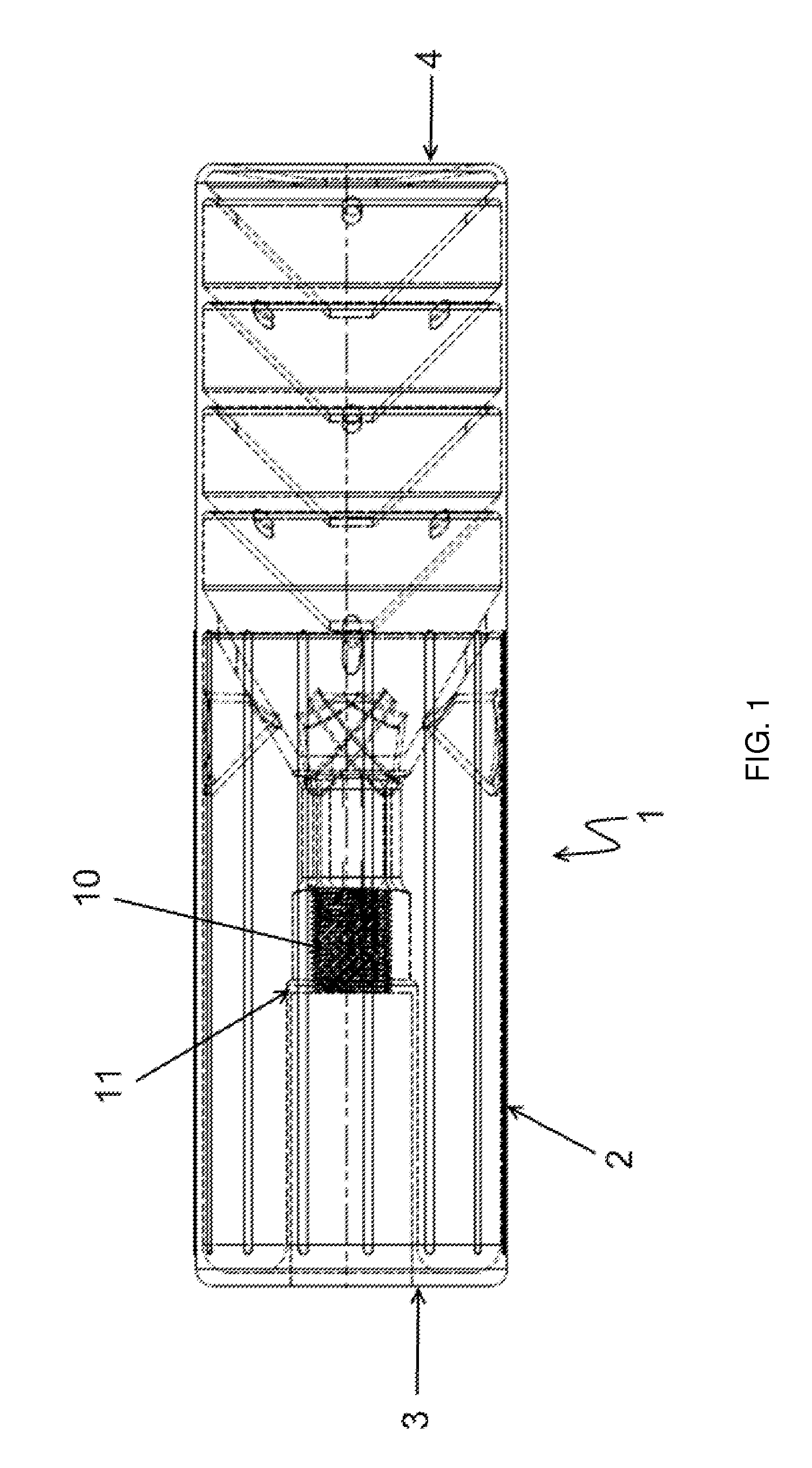
[0173]FIGS. 3, 4 and 6 show views of alternate embodiments of suppressors (29,30,31) according to the present invention. Identical numbers are used to refer to the components of suppressors (29-31) in FIGS. 3, 4, and 6 that are the same as the components of suppressor described with reference to FIGS. 1 and 2. However the arrangement / orientation of the baffles differ so as to facilitate provision of a suppressor that may be better suited to use with different types of guns.

fourth alternate embodiment

[0174]Referring now to FIGS. 9A-9D, showing a further embodiment of a suppressor (40).

[0175]The suppressor (40) has a substantially triangular cross section as is best shown in FIG. 9B.

[0176]The suppressor (40) has a first end wall (41), a second end wall (42), a first side wall (43), a second side wall (44), and a third side wall (45).

[0177]First end wall (41) has an aperture (46) into an overlap channel that is shown as (47) in FIG. 10C.

[0178]The first end wall (41), second end wall (42), and side walls (43-45) define a cavity (101).

[0179]A passageway, indicated by line (49) in FIG. 9C extends from aperture (46) through the cavity and to an aperture (47) in second end wall (42).

[0180]The suppressor (40) has an inner wall (102) and the second wall (103) that collectively form a double wall structure spacers (104) hold the walls (102, 103) apart from each other. There is a space (104) between the walls (102, 103) which acts to limit or reduce heat transfer from cavity (101) to secon...

fifth alternate embodiment

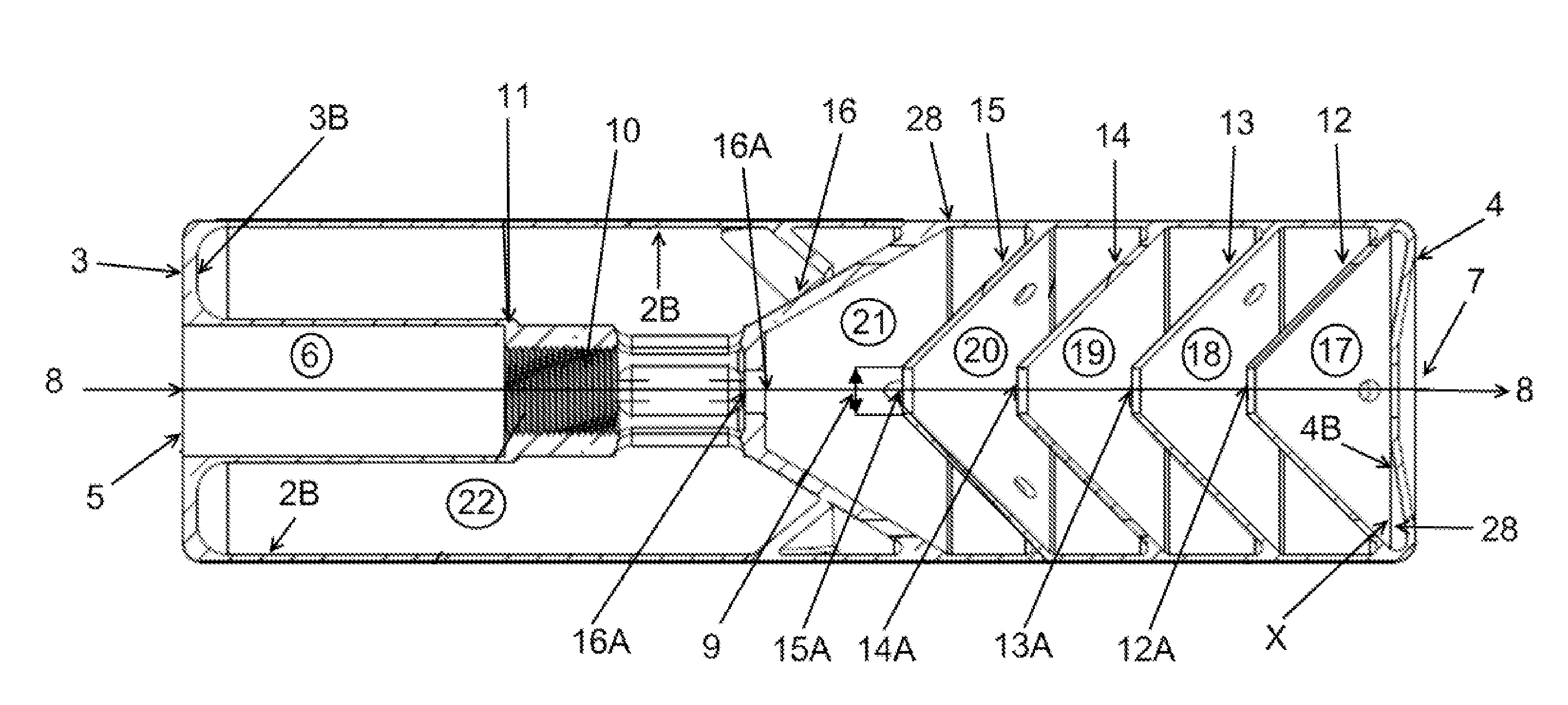
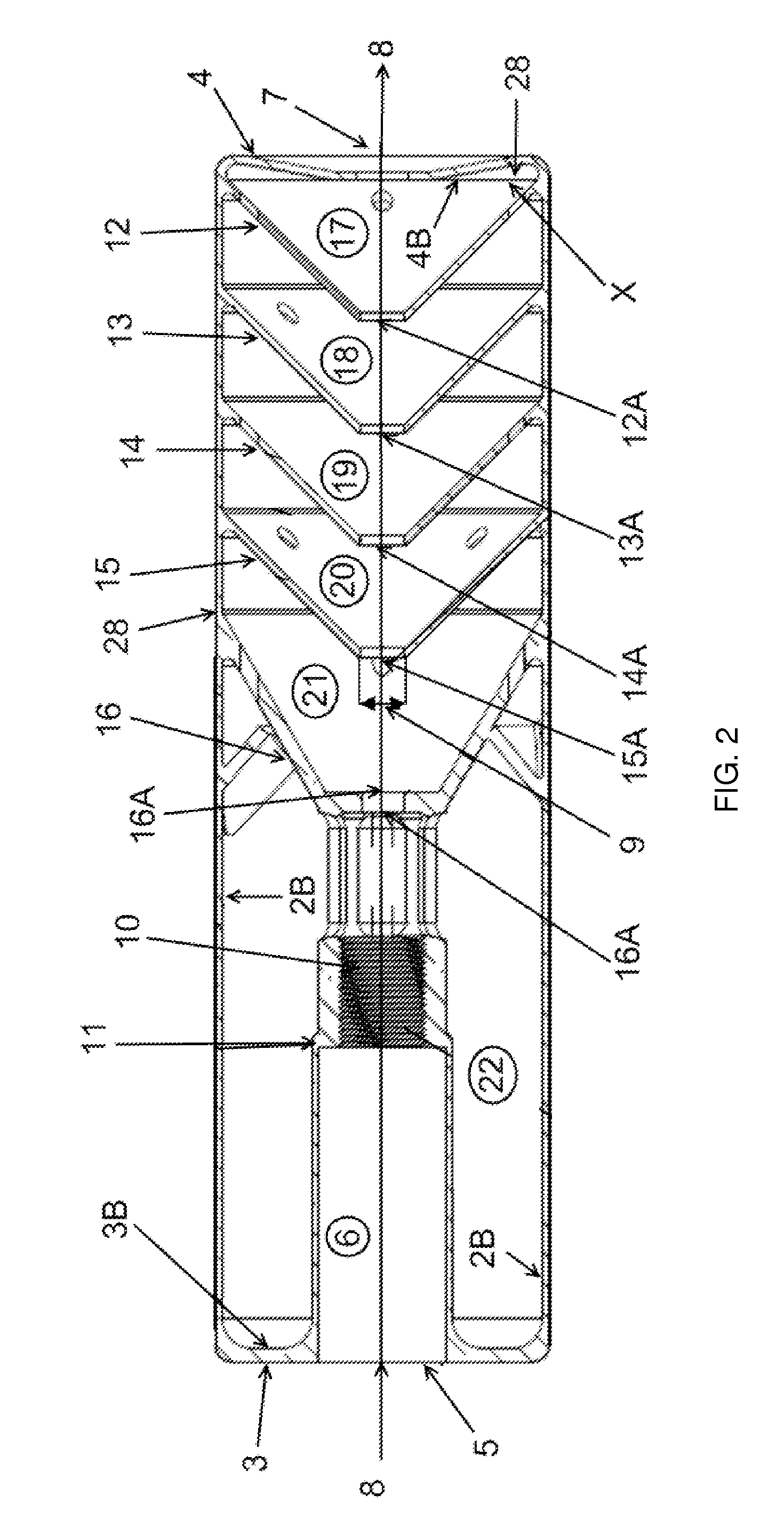
[0181]Referring now to FIG. 14 which is a side cross sectional view of suppressor (50) according to a fourth embodiment of the present invention.

[0182]The suppressor (50) has a housing formed by a continuous side wall (51), a first end wall (52) and a second end wall (53) which collectively define a cavity.

[0183]A series of baffles (54-60) are constructed so as to be integral to an inner surface of the side wall (2b). This is as discussed above in relation to FIGS. 13A, 13B, and 13C.

[0184]The suppressor (50) includes a series of fins (61-67) within the cavity. The fins (61-67) are all identical to each other and spaced apart along the length of the suppressor (50). Therefore only fin (61) will be described herein.

[0185]The bottom edge (68) of fin (61) has no support underneath. Therefore the fin (61) must be constructed out from inner surface (2b) of side wall (2) and downwards. As a result, fin (61) is constructed in a reverse direction e.g. downwards with respect to the build dire...


PUM

PropertyMeasurementUnit
Angleaaaaaaaaaa
Angleaaaaaaaaaa
Structureaaaaaaaaaa

Abstract

Methods and systems to manufacture gun suppressors using laser metal melting (LMM) are disclosed, together with gun suppressors manufactured according to the methods and systems. In preferred forms the LMM process involves deposition of a metal powder such as titanium oxide.

Description

STATEMENT OF CORRESPONDING APPLICATIONS[0001]This application is based on the specifications filed in relation to New Zealand Patent Application Numbers 605144 and 616919, the entire contents of which are incorporated herein by reference.TECHNICAL FIELD[0002]The present invention relates to improvements to suppressors and their methods of manufacture.BACKGROUND ART[0003]The weapons called guns use the expansion of a gas to propel a projectile. The gas can take several forms, such as compressed air stored in a canister attached to the gun. Alternatively, fire arms are a sub-type of gun, and use the expansion of a gas created by combustion to propel a projectile.[0004]A combustible material such as gun powder is stored within the projectile cartridge. A firing mechanism in the gun is used to ignite the combustible material. The combustion process creates the gas.[0005]The heat of combustion increases the temperature of the gas, which causes it to expand to an area of lower pressure. T...

Claims


Application Information

Patent Timeline
IPC IPC(8): F41A21/36F41A21/30B23K35/32B23K26/34
CPCB23K26/345B23K35/325F41A21/36F41A21/30B23K35/0244B23K35/0255B23K35/0272
Inventor WILSON, BERT, JOHN
Owner OCEANIA DEFENCE LTD
Why Eureka
Try Eureka