
System and method for controlling regenerating energy in an adjustable speed drive

a technology of adjustable speed and control method, which is applied in the direction of motor/generator/converter stopper, dynamo-electric converter control, ac motor accelaration/decelaration control, etc., can solve the problem of dc link voltage increase, afd trip, and disrupting normal stopping operation

Active Publication Date: 2015-01-01
EATON INTELLIGENT POWER LIMITED
View PDF1 Cites 10 Cited by
  • Summary
  • Abstract
  • Description
  • Claims
  • Application Information

AI Technical Summary

Benefits of technology

The present invention provides a system and method for controlled deceleration of a load during a regenerating operating condition using a dual loop control architecture. The technical effect of the invention is to provide a more efficient and accurate control system for adjusting the speed of a load, which can help to improve the overall performance and efficiency of the system.

Problems solved by technology

As energy is transferred from the motor to the DC link of the AFD, the DC link voltage increases and can become unstable.
If the DC link voltage rises above a threshold DC link voltage during deceleration, the AFD will trip and disrupt the normal stopping operation.
After the AFD trips, the motor shuts down in an uncontrolled manner.
The unstable DC link voltage and uncontrolled shutdown adds stress on the DC link capacitors, introduces EMC problems, creates undesirable harmonics and resonance, adds mechanical stress, and degrades overall system performance.
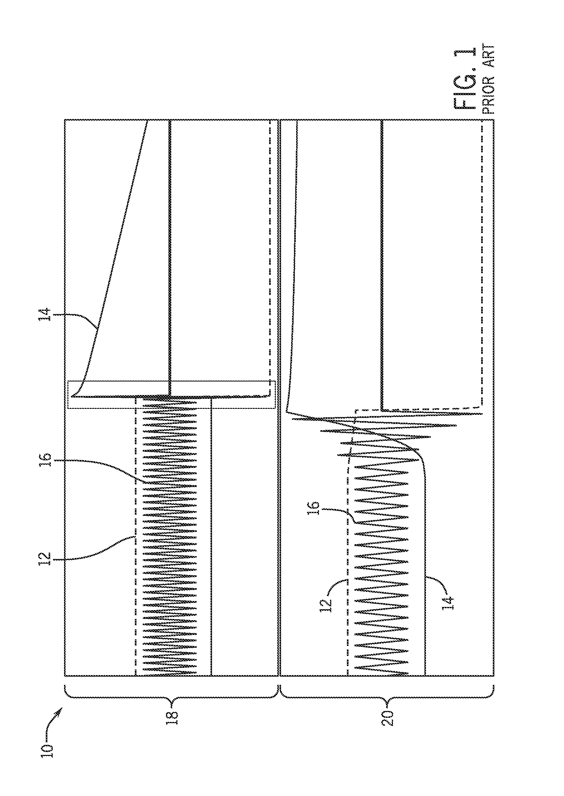
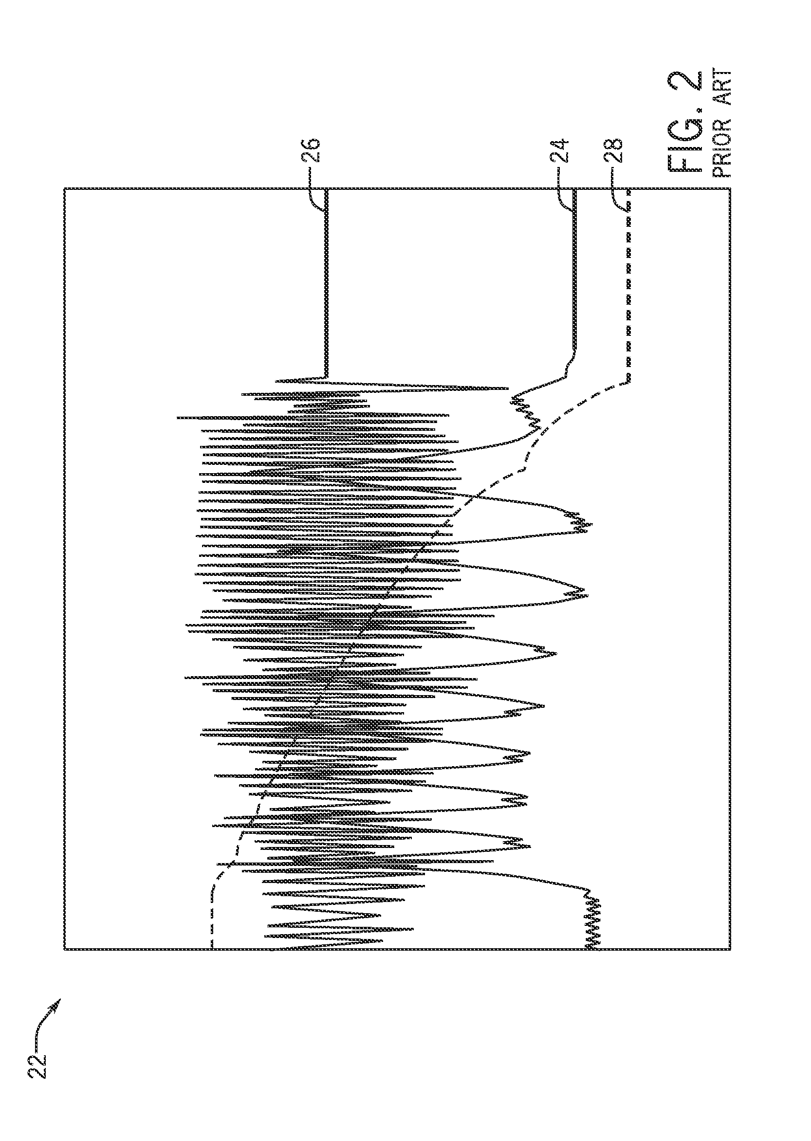
Instead of tripping, the switching control of the AFD may cause the DC link voltage to begin oscillating during the deceleration process.
That is, at certain frequencies, the voltage will jump between high and low values and disrupt the normal deceleration process, resulting in EMI and EMC interferences with surrounding equipment.
While the braking resistors can be effective in dissipating excess energy, the costs of the braking resistor can be significant.
Also, the large physical size of the braking resistor significantly increases the overall size of the AFD.

Method used


Image

  • System and method for controlling regenerating energy in an adjustable speed drive
  • System and method for controlling regenerating energy in an adjustable speed drive
  • System and method for controlling regenerating energy in an adjustable speed drive

Examples


Embodiment Construction

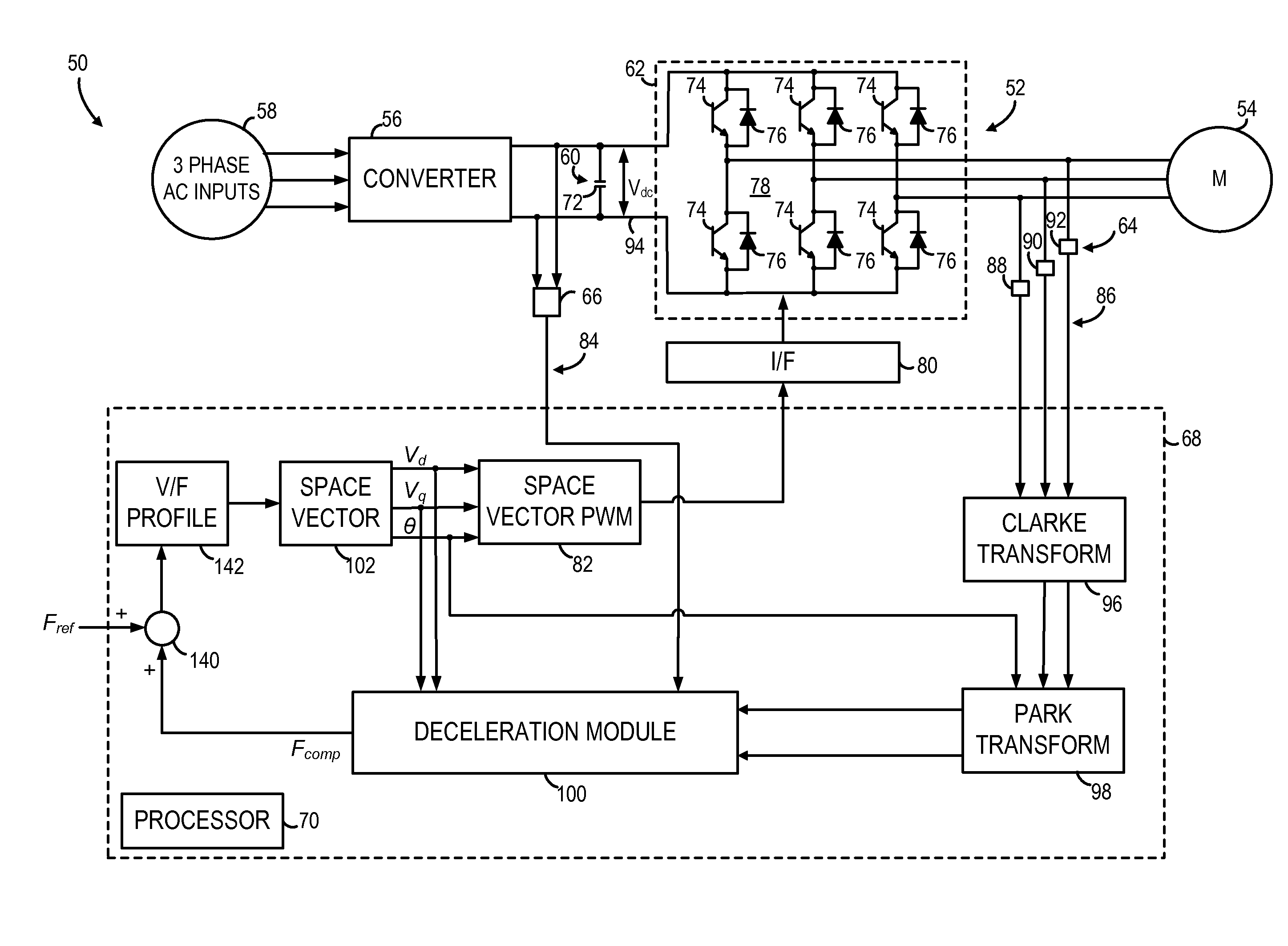
[0022]The embodiments of the invention set forth herein relate to electronic power converters and inverters and to a system and method that provides for controlled deceleration of a load during a regenerating operating condition. The system includes a dual loop control system that includes an outer control loop that regulates capacitor energy and an inner control loop that regulates power consumed by the load.

[0023]Referring to FIG. 3, a three-phase Adjustable Frequency Drive (AFD) system 50 is illustrated. AFD system 50 includes an Adjustable Frequency Drive (AFD) 52 designed to receive a three-phase alternating current (AC) power input, rectify the AC input, and perform a DC / AC conversion of the rectified segment into a three-phase alternating voltage of variable frequency and amplitude that is supplied to a load 54. In one embodiment, AFD 52 operates according to an exemplary V / Hz characteristic, described in more detail below. According to various embodiments, load 54 may be an ...


PUM


Abstract

A system and method for controlling an adjustable speed drive (ASD) to decelerate an AC load during a generating mode of operation is disclosed. The ASD includes a capacitor and an inverter coupled to a DC link. A current sensor system is coupled to an output of the inverter. The ASD further includes a control system programmed to calculate an energy of the capacitor, generate a reference power using the calculated capacitor energy, and calculate a feedback power from realtime current signals received from the current sensor system. The control system compares the feedback power to the reference power, defines a frequency offset based on the comparison, generates a speed command using the frequency offset, and outputs the speed command to the inverter to maintain a smooth DC link voltage during deceleration.

Description

BACKGROUND OF THE INVENTION[0001]The present invention relates generally to adjustable speed drives and, more particularly, to a system and method for controlling an adjustable speed drive during generating mode of operation during deceleration using a dual loop control architecture.[0002]Motor drives are frequently used in industrial applications to condition power and otherwise control electric driven motors such as those found with pumps, fans, compressors, cranes, paper mills, steel mills, rolling mills, elevators, machine tools, and the like. Motor drives typically provide a volts-per-hertz control and have greatly improved the efficiency and productivity of electric driven motors and applications. Increasingly, motor drives are taking the form of adjustable or variable speed drives (ASD or VSD) or adjustable frequency drives (AFD) that are adept at providing variable speed and / or variable torque control to an electric driven motor or induction machine.[0003]If the stator termi...

Claims


Application Information

Patent Timeline
IPC IPC(8): H02P23/00
CPCH02P23/00H02P23/0063H02P29/024H02P27/047H02M5/451H02P21/0021H02M2007/53876H02P23/20H02P23/28H02P29/0241H02M7/53876H02P3/18H02P27/06
Inventor MO, YAOJINLI, HUAQIANGYU, ANBOLI, DAWEIXIE, JINGFENG
Owner EATON INTELLIGENT POWER LIMITED
Learn More