Pitch bearing assembly with stiffener

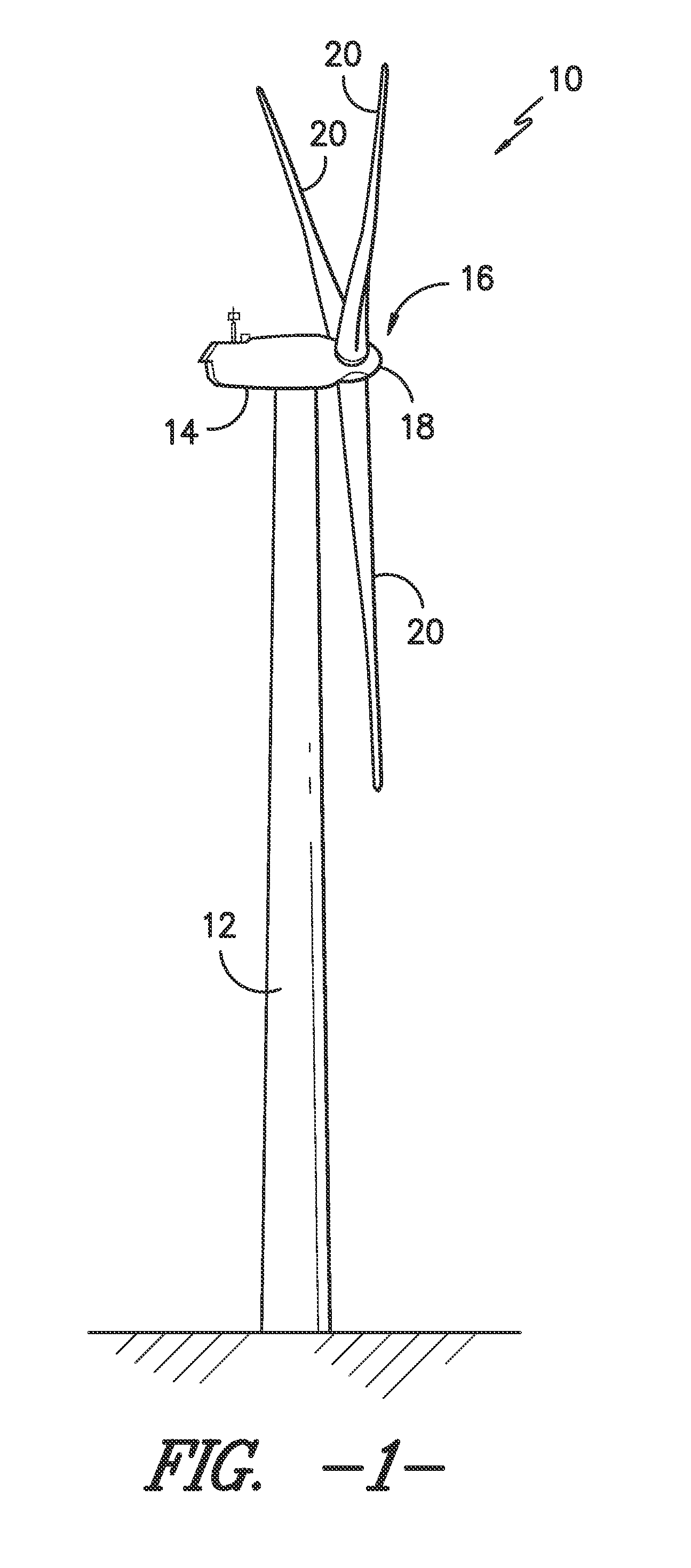
a technology of pitch bearings and stiffeners, which is applied in the direction of liquid fuel engines, vessel construction, marine propulsion, etc., can solve the problems of affecting the performance of the rotor blade, the rotor blades may be longer, and the pitch bearings are often subject to extreme, varying and/or opposing loads, and the damage to the pitch bearings is substantial

Active Publication Date: 2015-01-01
GENERAL ELECTRIC CO
View PDF8 Cites 26 Cited by
  • Summary
  • Abstract
  • Description
  • Claims
  • Application Information

AI Technical Summary

Problems solved by technology

Thus, longer rotor blades may be subject to increased loading, particularly when a wind turbine is operating in high-speed wind conditions.
Thus, due to the stiffness differential between the hub and the rotor blades, the pitch bearings are often subjected to extreme, varying and / or opposing loads.
This variation in loading across the inner and outer races can result in substantial damage to the pitch bearings.

Method used


Image

  • Pitch bearing assembly with stiffener
  • Pitch bearing assembly with stiffener
  • Pitch bearing assembly with stiffener

Examples


Embodiment Construction

[0027]Reference now will be made in detail to embodiments of the invention, one or more examples of which are illustrated in the drawings. Each example is provided by way of explanation of the invention, not limitation of the invention. In fact, it will be apparent to those skilled in the art that various modifications and variations can be made in the present invention without departing from the scope or spirit of the invention. For instance, features illustrated or described as part of one embodiment can be used with another embodiment to yield a still further embodiment. Thus, it is intended that the present invention covers such modifications and variations as come within the scope of the appended claims and their equivalents.

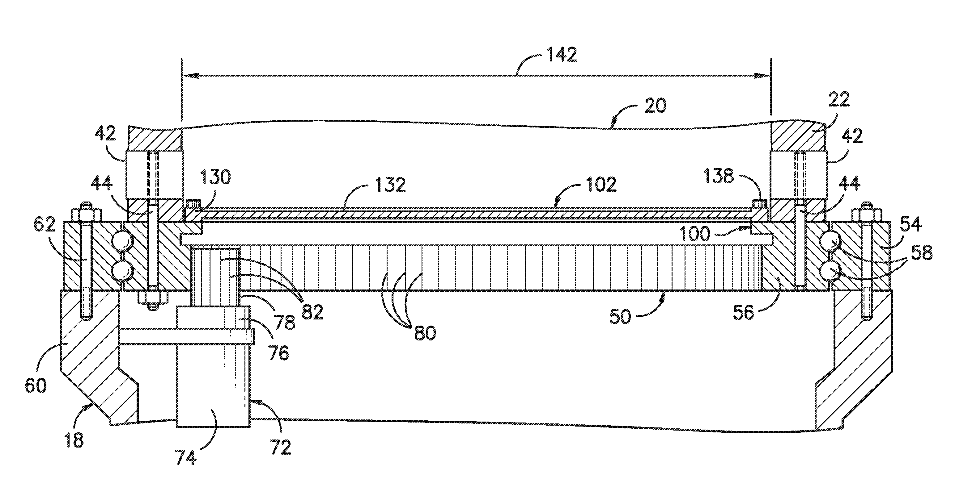
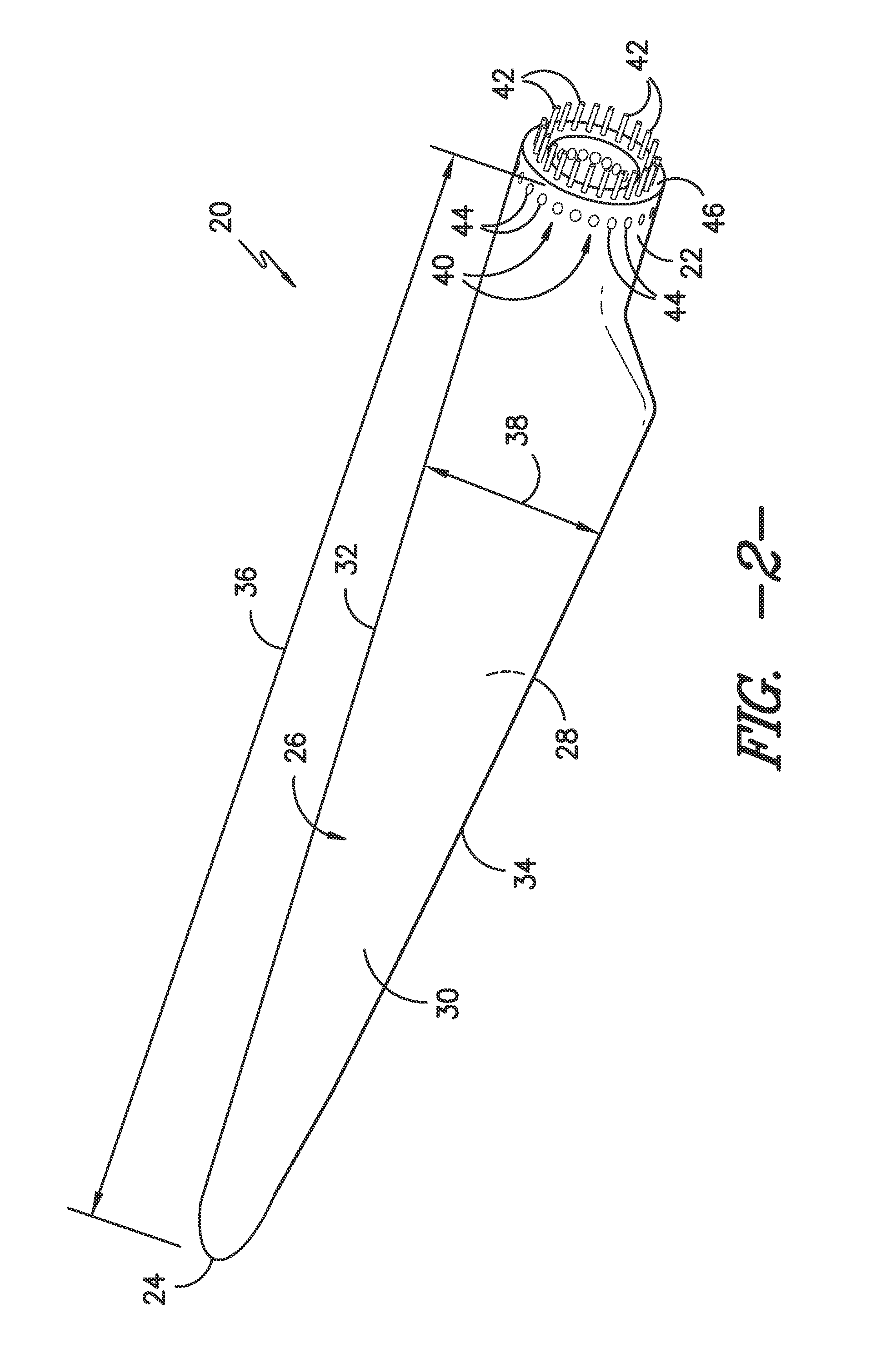
[0028]In general, the present subject matter is directed to a pitch bearing assembly for a wind turbine that is configured to support a stiffener for stiffening the pitch bearing at the interface between the bearing and one of the rotor blades of the wind t...


PUM


Abstract

A pitch bearing assembly for a wind turbine may include an outer race and an inner race rotatable relative to the outer race. The inner race may define an inner circumference and may include a plurality of gear teeth around the inner circumference. The inner race may also include a circumferential flange extending at least partially around the inner circumference. In addition, the pitch bearing assembly may include a stiffener coupled to the circumferential flange.

Description

FIELD OF THE INVENTION[0001]The present subject matter relates generally to wind turbines and, more particularly, to a pitch bearing assembly for a wind turbine having a circumferential flange for mounting a stiffener to the pitch bearing.BACKGROUND OF THE INVENTION[0002]Wind power is considered one of the cleanest, most environmentally friendly energy sources presently available, and wind turbines have gained increased attention in this regard. A modern wind turbine typically includes a tower, generator, gearbox, nacelle, and one or more rotor blades. The rotor blades capture kinetic energy from wind using known airfoil principles and transmit the kinetic energy through rotational energy to turn a shaft coupling the rotor blades to a gearbox, or if a gearbox is not used, directly to the generator. The generator then converts the mechanical energy to electrical energy that may be deployed to a utility grid.[0003]To ensure that wind power remains a viable energy source, efforts have ...

Claims


Application Information

Patent Timeline
Patent Type & Authority Applications(United States)
IPC IPC(8): F16C33/60F16C19/08F16C33/58F03D7/02
CPCF03D7/0224F16C33/60F16C33/583F16C19/08F03D11/0008F03D1/0658F05B2260/79F16C19/18F16C33/581F16C2360/31F03D80/70F16C2300/14F16C35/06Y02E10/72F16C35/045F16C35/042
Inventor MINADEO, ADAM DANIELGEVERS, WILLIAM FRANCISPINE, ROBERT DAVISSCHUBERT, ANDREAS
Owner GENERAL ELECTRIC CO
Why Eureka
Try Eureka