Apparatus and method for digital radiography

a digital radiography and apparatus technology, applied in the field of digital radiography, can solve the problems of not revealing cephalographic imaging and secondary collimation for cephalography, significant artifacts in reconstructed images, and the maximum allowable field of view (fov) cannot cover the patient, so as to achieve convenient adjustment and optimize the process. the effect of process and workload

Active Publication Date: 2015-01-08
DE GOTZEN
View PDF1 Cites 19 Cited by
  • Summary
  • Abstract
  • Description
  • Claims
  • Application Information

AI Technical Summary

Benefits of technology

[0091]Of course when the modulation is performed automatically in response to a morphological aspect of the patient, the reliability of the process and the workload of the operator can be optimized.
[0092]In a further embodiment, the modulation can also be advantageously performed automatically in real t

Problems solved by technology

EP 1752099 teaches about a combined apparatus for panoramic and CT imaging modes, having adjustable magnification ratio and about a mounting part for attaching and detaching the suitable X-ray detector; however, it does not disclose cephalographic imaging and secondary collimation for cephalography.
In many implementations of cone-beam CT in radiotherapy for target positioning, it is not uncommon that the maximum allowable field of view (FOV) cannot cover the patient because of the limited size of the flat-panel detector.
In this situation, the measurements will contain truncated projections, leading to significant artifacts in reconstructed images.
With increasing detector asymmetry, however, the modified FDK algorithm may produce significant aliasing artifacts.
If an explicit data rebinning process is not invoked, this data acquisition configuration will reek havoc on many known fan-beam image reconstruction schemes including the standard filtered backprojection (FBP) algorithm and the super-short-scan FBP reconstruction algorithms.
However, we demonstrate th

Method used


Image

  • Apparatus and method for digital radiography
  • Apparatus and method for digital radiography
  • Apparatus and method for digital radiography

Examples


Embodiment Construction

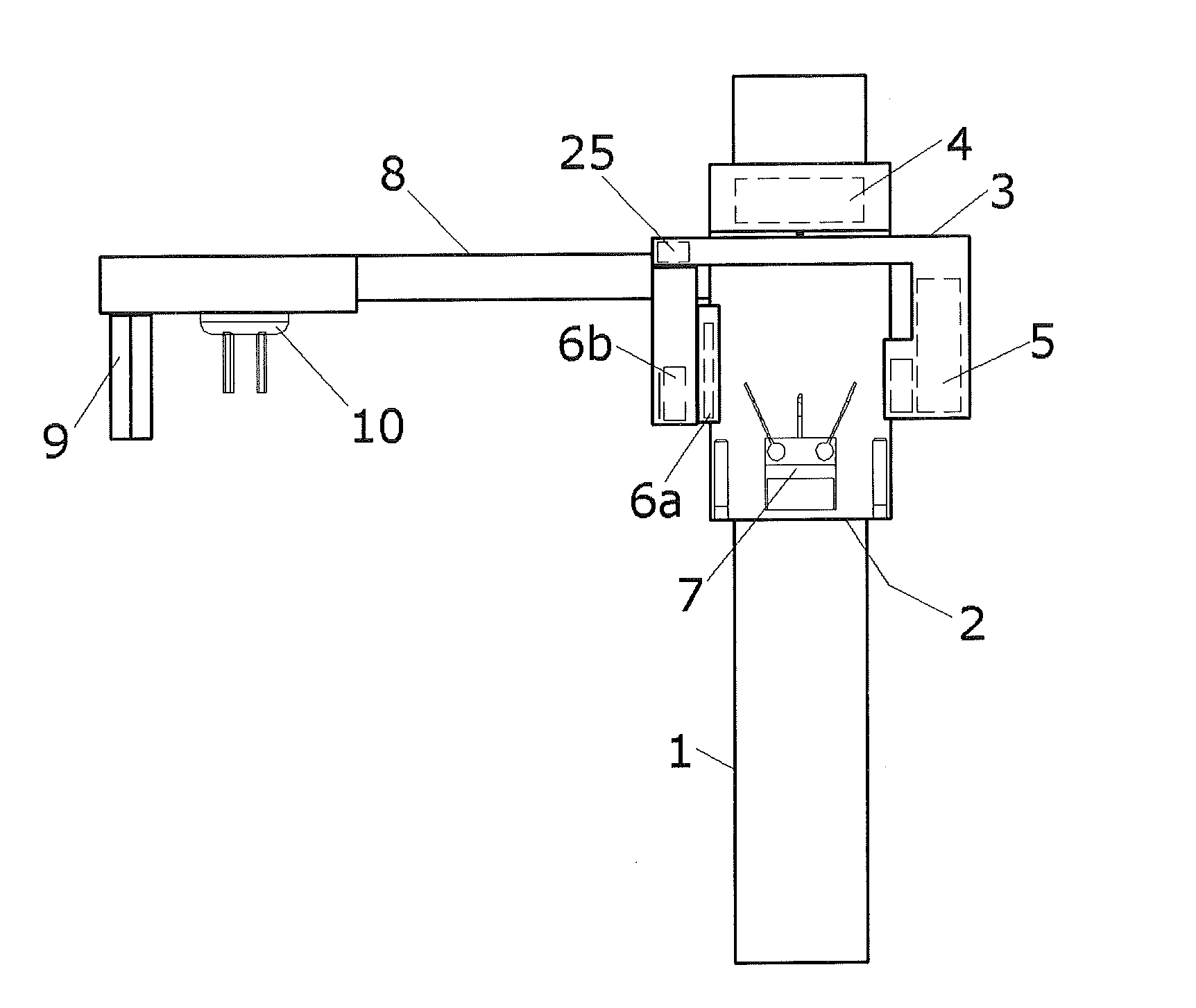
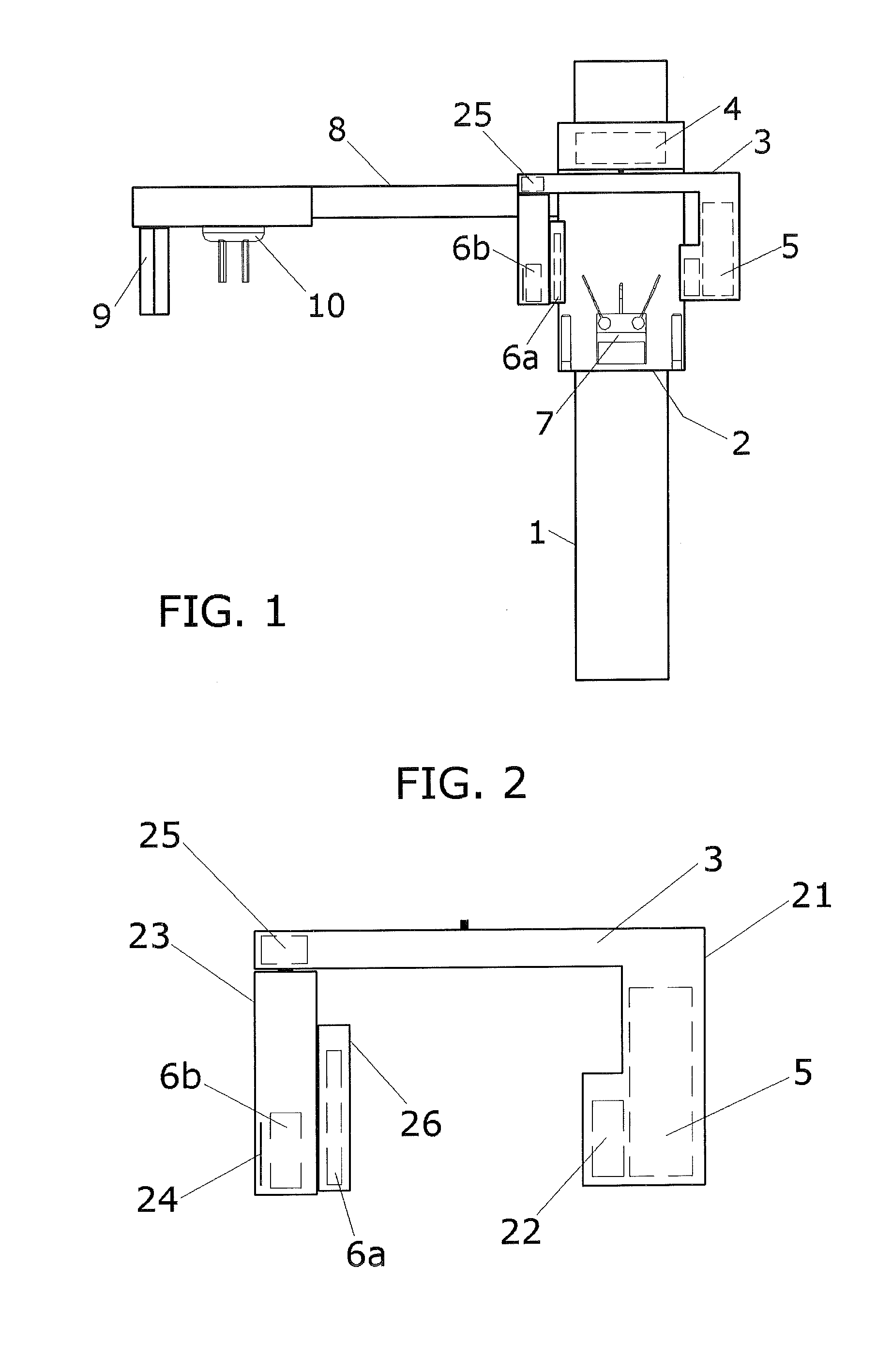
[0101]According to a preferred embodiment, the imaging system of the present invention is based on a combined diagnostic x-ray system for panoramic, CT (Computed Tomography) and cephalometric examinations of the human skull.

[0102]Such apparatus is described in FIG. 1, where a column (1) supports vertically a sliding carriage (2) capable of vertical sliding along the column to adjust for a patient height.

[0103]The carriage (2) supports a rotating arm (3), by a cinematic unit (4) capable of driving the same rotating arm (3) according to rotational and translational movements.

[0104]The rotating arm (3) holds a x-ray generator (5) opposite to a panoramic x-ray detector (6a) and a CT x-ray detector (6b).

[0105]For panoramic and CT imaging, the patient is positioned below the rotating arm (3), in between the x-ray generator (5) and the x-ray detectors (6a) and (6b), supported and aligned by the patient positioning system (7).

[0106]The carriage (2) also holds a lateral arm (8) utilized for ...


PUM


Abstract

An X-ray apparatus for digital radiography has a rotating arm where the X-ray source and X-ray sensor cassette are oppositely mounted. The source has a primary collimator to adjust the X-ray beam size according to the selected imaging modality. The sensor cassette encloses a first X-ray detector for a first imaging mode, while a second X-ray detector usable for a second imaging mode is detachably mounted on the external side of the sensor cassette. The sensor cassette accommodates a second collimator to create a fan shaped X-ray beam for a third imaging modality. The sensor cassette has a linear motorized movement which is used for: aligning the X-ray beam with respect to the first and second detector; positioning the first detector in the first imaging mode to achieve an extended view; and scanning movement during the third imaging modality synchronized with the horizontal movement of a third X-ray detector.

Description

FIELD OF THE INVENTION[0001]The invention relates to a method for Digital Radiography by means of a combined multi-sensor X-ray imaging apparatus, capable of performing according to multiple imaging modes, the method comprising the steps of:[0002]Positioning an object in between a radiation source and a x-ray detector using an object support and positioning system;[0003]Selecting a radiographic imaging modality and a desired region of interest;[0004]Adjusting, by one or more x-ray collimators, the shape of the x-ray beam according to the selected imaging modality;[0005]Positioning the X-ray detector in a predefined position into the X-ray beam;[0006]Generating X-ray radiation by the radiation source;[0007]Performing a movement for scanning of the object while detecting the X-ray radiation by means of the x-ray detector;[0008]Performing a readout of the x-ray detector image data, acquisition and elaboration in order to obtain a processed image or tridimensional data set of the select...

Claims


Application Information

Patent Timeline
IPC IPC(8): A61B6/00A61B6/14A61B6/03
CPCA61B6/4078A61B6/14A61B6/032A61B6/06A61B6/4035A61B6/4266A61B6/4291A61B6/4417
Inventor ROTONDO, GIUSEPPELISSANDRELLO, FABIOGIANI, CLAUDIO
Owner DE GOTZEN
Why Eureka
Try Eureka