

Electronic device, method of manufacturing electronic device, physical quantity sensor, electronic apparatus, moving object
a manufacturing method and electronic device technology, applied in the direction of acceleration measurement using interia forces, instruments, coatings, etc., can solve the problems of deterioration of the electric property of the electronic device, low sensor sensitivity,
- Summary
- Abstract
- Description
- Claims
- Application Information
AI Technical Summary
Benefits of technology
Problems solved by technology
Method used
Image

Examples
first embodiment
Modification of First Embodiment
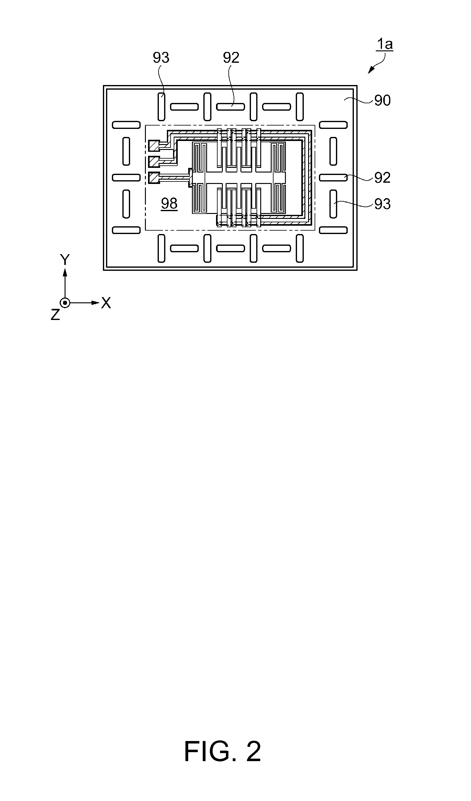
[0103]Here, a modification of the physical quantity sensor 1 according to the first embodiment will be described with reference to FIG. 2. FIG. 2 is a schematic drawing illustrating a modification of the physical quantity sensor 1 according to the first embodiment. A physical quantity sensor 1a of the modification illustrated in FIG. 2 is different from the configuration of the physical quantity sensor 1 of the first embodiment in the groove portions formed in the outer edge portion 90 (the first grooves 92 in the physical quantity sensor 1). In the following description about the physical quantity sensor 1a in the modification, only different points from the physical quantity sensor 1 are mainly described, and the same configuration may be denoted by the same reference signs and the repeated description may be omitted.
[0104]A physical quantity sensor 1a illustrated in FIG. 2 includes a first sensor element (first functional element) 98 as a sensor po...
second embodiment
[0111]First of all, a physical quantity sensor of an electronic device according to a second embodiment will be described. FIGS. 3A to 3C are schematic drawings illustrating a physical quantity sensor of the electronic device according to the second embodiment. FIG. 3A is a plan view, FIG. 3B is a plan view of the sensor element of the physical quantity sensor, and FIG. 3C is a cross-sectional view taken along the line A-A in FIG. 3B. In the following example, description will be given with an X-direction as a rightward direction, an X-axis direction (±X direction) as a lateral direction, a Y-direction as a depth direction, a Y-axis direction (±Y direction) as a fore-and-aft direction, a Z-direction corresponds to an upward direction, and Z-axis direction (±Z direction) as a vertical direction or the thickness direction of the substrate 10 described later in XYZ axes shown in the drawings for the sake of convenience of explanation.
Configuration of Physical Quantity Sensor
[0112]A phy...
fifth embodiments
Third to Fifth Embodiments
[0170]Subsequently, physical quantity sensors according to the third to the fifth embodiments will be described with reference to FIGS. 6A to 6C. In the description, portions having the same configurations as those described in the second embodiment are denoted by the same reference signs, and overlapped description will be omitted. In the third to the fifth embodiments given below, description may be given with an X-direction as a rightward direction, an X-axis direction (±X direction) as a lateral direction, a Y-direction as a depth direction, a Y-axis direction (±Y direction) as a fore-and-aft direction, a Z-direction corresponds to an upward direction, and Z-axis direction (±Z direction) as a vertical direction or the thickness direction of the substrate 10 described later in XYZ axes shown in FIGS. 6A to 6C for the sake of convenience of explanation.
PUM
| Property | Measurement | Unit |
|---|---|---|
| Thickness | aaaaa | aaaaa |
| Area | aaaaa | aaaaa |
| Symmetry | aaaaa | aaaaa |
Abstract
Description
Claims
Application Information