Microparticle sensor

a technology of microparticles and sensors, applied in the field of sensors, can solve the problems of particulate sensors failing to accurately detect the amount of particulates in exhaust gas, the electric potential of floating potential sections failing to accurately reflect the amount of ions used for electric charging, and partially exposed electrically conductive members

Active Publication Date: 2015-01-22
NGK SPARK PLUG CO LTD
View PDF4 Cites 26 Cited by
  • Summary
  • Abstract
  • Description
  • Claims
  • Application Information

AI Technical Summary

Benefits of technology

[0008]An object of the present invention is to elongate service life of a particulate sensor for detecting the amount of particulates in gas which contains particulates, through utilization of a configuration in which electric potential varies with the amount of ions used for electrically charging particulates or the amount of ions not used for electrically charging particulates.Means for Solving the Problem
[0031]In such a mode as application example 2, the sensor ground section forms a Faraday shield. Current which leaks from the first electrode and the discharge potential portion flows into the sensor ground section which surrounds the first electrode and the discharge potential portion. As a result, the sensor ground section can have an electric potential which accurately reflects the amount of ions trapped by the capture section. Thus, the particulate sensor can accurately detect the amount of particulates in gas on the basis of the potential of the sensor ground section.
[0032]Employment of such a mode as application example 3 can reduce the possibility of occurrence of a short circuit, caused by adhesion of particulates, etc., between electrically conductive members of the sensor unit, such as the sensor ground section and the discharge potential portion.
[0035]In a mode in which a protector as in the case of application example 6 is not provided, a structure whose temperature is increased by the heater may possibly be ruptured as a result of a locally abrupt temperature variation caused by adhesion of a water droplet on the heated structure. However, through employment of the above-mentioned mode, even when gas contains water droplets, there can be reduced the possibility of rupture of the structure caused by adhesion of a water droplet on the structure.

Problems solved by technology

Furthermore, such electrically conductive members are partially exposed to the interior of the exhaust gas pipe.
In such a condition, the electric potential of the floating potential section fails to accurately reflect the amount of ions used for electric charging.
As a result, the particulate sensor fails to accurately detect the amount of particulates in exhaust gas.
Such a problem is widely involved in not only particulate sensors used for detecting soot in exhaust gas of internal combustion engines but also particulate sensors for detecting the amount of particulates in gas which contains particulates, through utilization of a configuration in which electric potential varies with the amount of ions used for electrically charging particulates or the amount of ions not used for electrically charging particulates.

Method used


Image

  • Microparticle sensor
  • Microparticle sensor
  • Microparticle sensor

Examples


first embodiment

A. First Embodiment

A1. Configuration of Particulate Sensor:

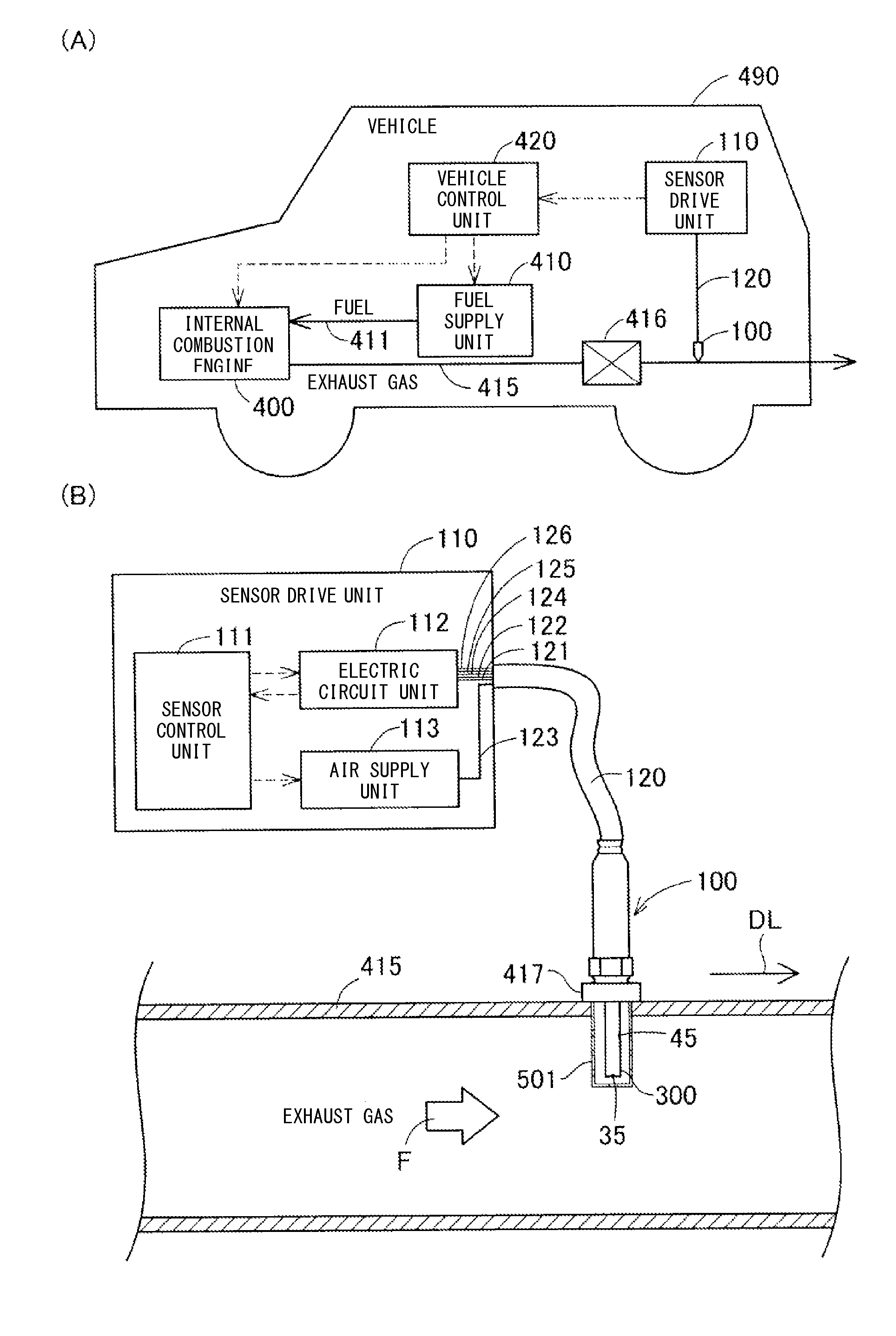
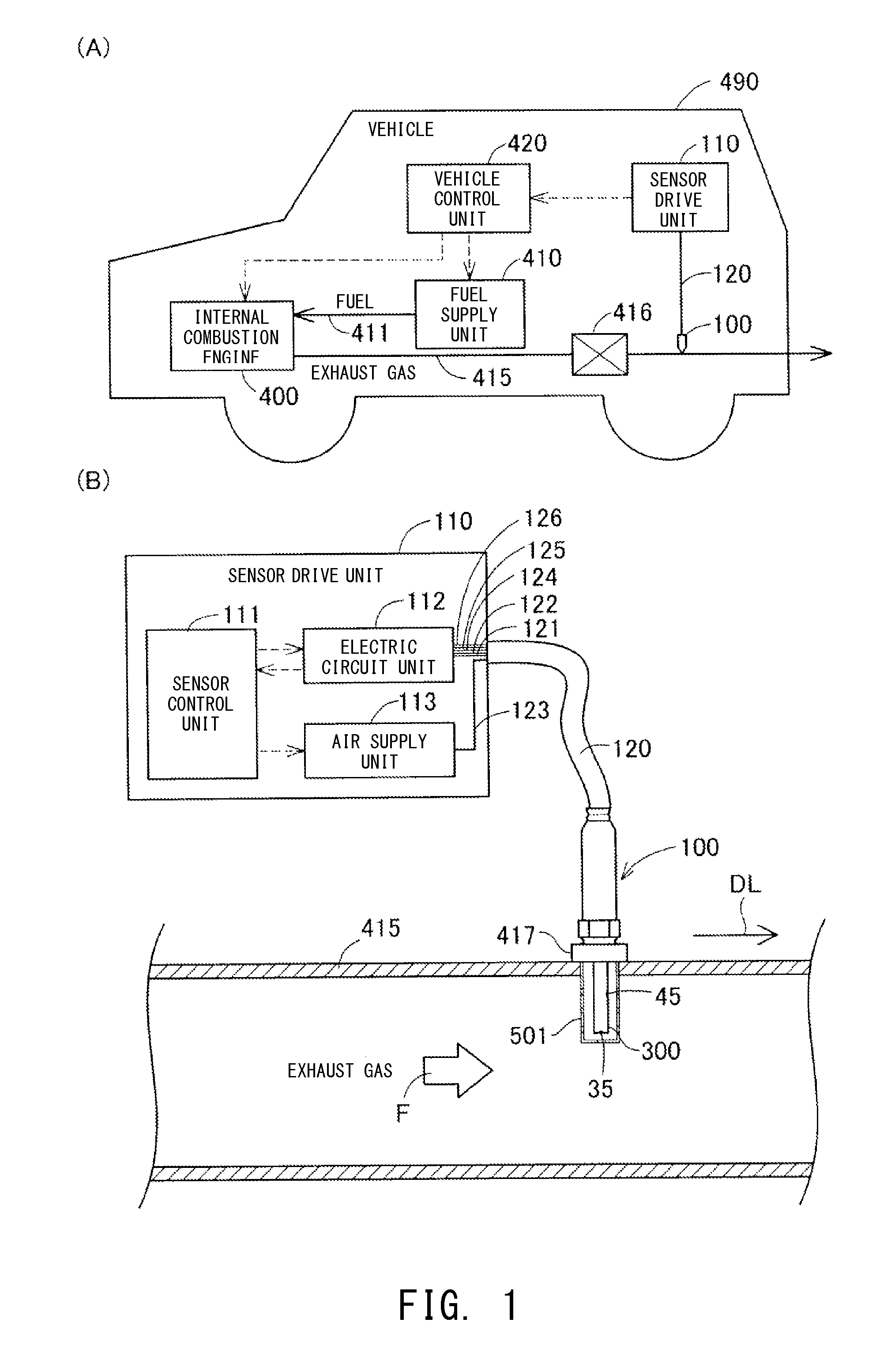
[0044]FIG. 1 is a set of schematic views showing the configuration of a vehicle equipped with a particulate sensor according to an embodiment of the present invention, and the configuration of a sensor drive unit for controlling the particulate sensor. As shown in FIG. 1(A), a vehicle 490 includes an internal combustion engine 400, a fuel supply unit 410, and a vehicle control unit 420. The internal combustion engine 400 is a power source of the vehicle 490 and can be, for example, a diesel engine.

[0045]The fuel supply unit 410 supplies fuel to the internal combustion engine 400 through a fuel pipe 411. An exhaust gas pipe 415 is connected to the internal combustion engine 400, and exhaust gas from the internal combustion engine 400 is discharged to the exterior of the vehicle 490 through the exhaust gas pipe 415. A filter device 416 (e.g., DPF (Diesel Particulate Filter): diesel particulate collection filter) for removing p...

modification 1

B1.

[0143]In the embodiment described above, air is used for leading the ions PI generated in the ion generation section IG to the electric charge section EC and the capture section CP. However, gas utilized for leading the ions PI to the electric charge section EC and the ion capture section CP can be another gas which does not contain particulates to be detected. Preferably, gas utilized for leading the ions PI to the electric charge section EC and the capture section CP is unlikely to be ionized in an environment where the particulate sensor 100 is used. More preferably, gas utilized for leading the ions PI to the electric charge section EC and the capture section CP is ionized through corona discharge. Furthermore, preferably, the gas exists around the particulate sensor 100 and the sensor drive unit 110 in an environment where the particulate sensor 100 is used.

B2. Modification 2:

[0144]In the embodiment described above, a nozzle is formed at the forward end portion 611n of the c...

modification 5

B5.

[0148]In the embodiment described above, the portion 323 other than the distal end portion 322 of the discharge pattern 320, the portion 327 other than the distal end portion 326 of the trap pattern 325, the first ground pattern 340, the vias 310v of the first ceramic layer 310, and the vias 330v3 of the second ceramic layer 330 are provided in the interior of the structure ST made of insulating ceramic. However, electrically conductive members in regions in noncontact with gas which contains particulates to be detected may be exposed to the exterior of the structure.

B6. Modification 6:

[0149]In the embodiment described above, the vias 310v of the first ceramic layer 310 and the vias 330v of the second ceramic layer 330 are provided along three sides of the rectangular cross section of the structure ST of the sensor unit 300. The first ground pattern 340 forms a plane perpendicular to the vias 310v and 330v in the interior of the rectangular columnar structure ST. In the embodimen...


PUM

PropertyMeasurementUnit
currentaaaaaaaaaa
electric potentialaaaaaaaaaa
voltageaaaaaaaaaa

Abstract

A particulate sensor including a sensor unit (300) having an ion generation section (611, 361, 322); an electric charge section (612) for electrically charging at least portion of particulates S using ions PI; a capture section (616, 617, 316, 326, 362) for trapping at least portion of the ions PI not used for electrically charging the particulates S; and a sensor ground section (340, 310v, 330v3) connected to the capture section and having a first floating potential corresponding to the amount of the ions PI trapped by the capture section. The sensor unit can detect the amount of the particulates S in the gas on the basis of the electric potential of the sensor ground section. The sensor ground section is covered with insulating ceramic at that outer portion of the sensor unit which comes into contact with the gas.

Description

TECHNICAL FIELD[0001]The present invention relates to a sensor for detecting the amount of microparticles (particulates), such as soot, contained in exhaust gas.BACKGROUND ART[0002]Exhaust gas from an internal combustion engine such as a diesel engine contains particulates such as soot. In order to control or restrain the amount of particulates contained in exhaust gas which is exhausted from an internal combustion engine to the atmosphere, a particulate sensor for detecting the amount of particulates in exhaust gas may be attached to an exhaust gas pipe of the internal combustion engine. Such a particulate sensor is known to detect the amount of particulates in exhaust gas by generating ions through corona discharge, and electrically charging particles in exhaust gas by use of portion of the generated ions (Patent Document 1, etc., mentioned below).[0003]The particulate sensor mentioned above has a floating potential section whose electric potential varies with the amount of ions u...

Claims


Application Information

Patent Timeline
Patent Type & Authority Applications(United States)
IPC IPC(8): G01N33/00G01N27/02G01N15/10G01M15/10
CPCG01N15/1031G01M15/102G01N33/0036G01N27/02G01N15/0656G01N1/2252F01N2560/02F01N2560/05G01N33/0027G01N2291/02408
Inventor MOTOMURA, MASAYUKISUGIYAMA, TAKESHITASHIMA, KEISUKEOSAWA, NORIMASAMATSUOKA, TOSHIYAYOKOI, HITOSHI
Owner NGK SPARK PLUG CO LTD
Why Eureka
Try Eureka