Variable series resistance termination for wireline serial link transistor

Active Publication Date: 2015-01-22
ADVANCED MICRO DEVICES INC
View PDF7 Cites 2 Cited by
  • Summary
  • Abstract
  • Description
  • Claims
  • Application Information

AI Technical Summary

Benefits of technology

The present patent is about a resistive tuning circuit for wireline serial link transmitters and receivers in integrated circuits. The circuit reduces parasitic capacitance and degradation in signal quality caused by imperfect return loss caused by reflection of signals. The circuit includes a termination circuit formed of resistive components that can be selectively coupled in series between a termination voltage node and a pad that is coupled to the wireline serial link. By selectively coupling more or fewer resistive components in series, the capacitive component of the impedance can be reduced, resulting in reduced return loss and improved signal quality. The resistive tuning circuit can be controlled using enabling signals to transistors coupled between the resistive components and the termination voltage node or pad. The technical effect of the resistive tuning circuit is to improve the performance of high-speed wireline serial link transmitters and receivers in integrated circuits.

Problems solved by technology

Signals transmitted from a transmitter to a receiver over a high-speed wireline serial link may be degraded by imperfect return loss caused by reflection of a portion of the signal at a discontinuity such as an impedance mismatch between the transmitter and the receiver.
At higher frequencies, degradation in return loss caused by reflections is primarily caused by the capacitive component of the port impedance at the transmitter.
The presence of these transistors incurs a parasitic capacitance, which increases the high-frequency return loss and degrades the transmitted signal.

Method used


Image

  • Variable series resistance termination for wireline serial link transistor
  • Variable series resistance termination for wireline serial link transistor
  • Variable series resistance termination for wireline serial link transistor

Examples


Embodiment Construction

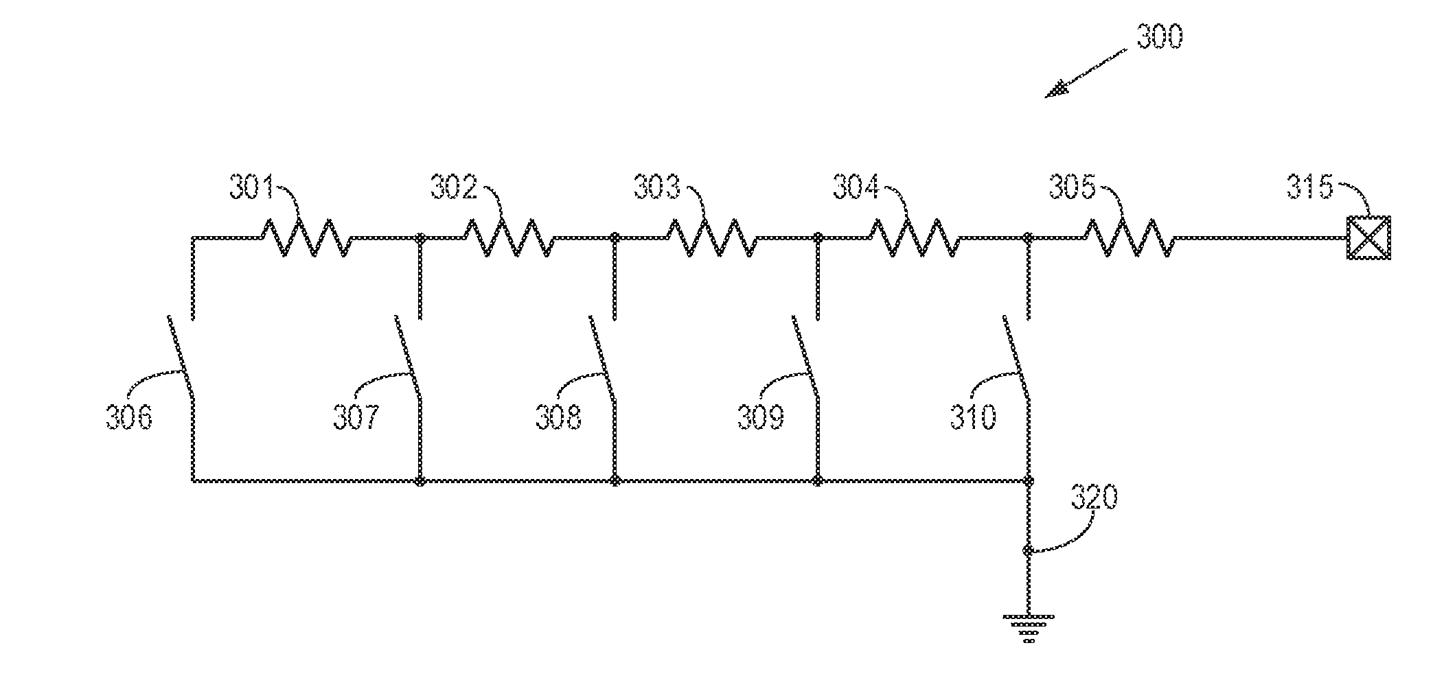
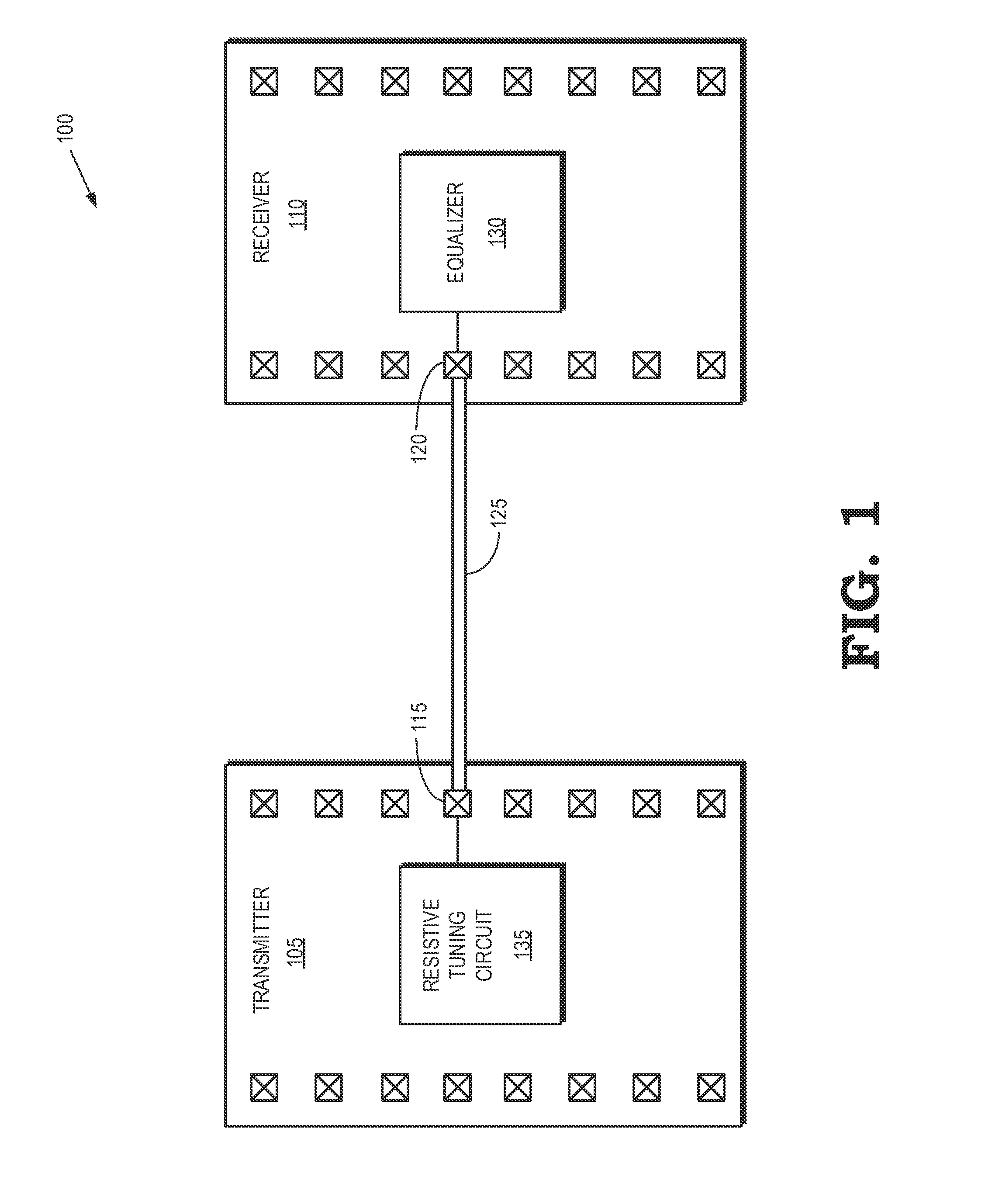
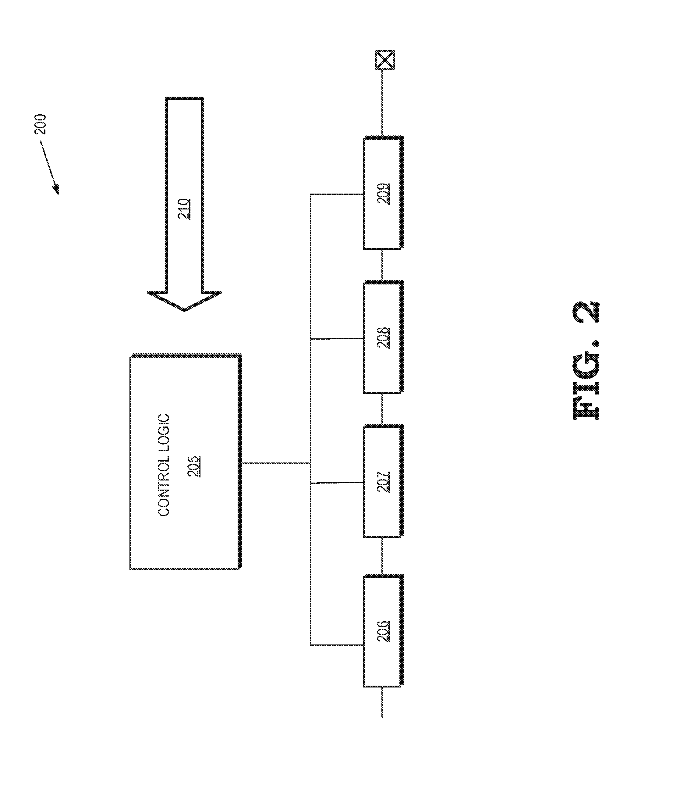
[0014]FIGS. 1-6 describe embodiments of a resistive tuning circuit that may be implemented in a transmitter or a receiver that communicates over a wireline serial link and which may exhibit reduced parasitic capacitance. The resistive tuning circuit includes a termination circuit formed of a plurality of resistive components such as one or more resistors coupled in series to reduce the capacitive component of the impedance of the transmitter or receiver. Some embodiments of the termination circuit are implemented using a plurality of resistive components that can be selectively coupled in series between a termination voltage node and a pad that is configured to be coupled to the wireline serial link. The resistive component of the impedance can be varied by selectively coupling more or fewer of the resistive components in series between the termination voltage node and the pad. The capacitive component of the impedance is produced by the parasitic capacitance of switches such as tra...


PUM


Abstract

A variable series resistance termination circuit for wireline serial link transceivers is provided. Some embodiments include a pad for coupling to a wireline serial link and a termination circuit. The termination circuit includes a plurality of resistive components coupled in series with the pad and a plurality of switches. Each switch is to couple one or more of the plurality of resistive components in series between the pad and a termination voltage node when the switch is closed. A subset of the plurality of switches can be selectively closed to establish a resistive component of an impedance of the termination circuit.

Description

BACKGROUND[0001]1. Field of the Disclosure[0002]The present disclosure relates generally to integrated circuits and, more particularly, to wireline serial link transceivers in integrated circuits.[0003]2. Description of the Related Art[0004]High-speed wireline serial links may be used to interconnect portions of an integrated circuit. For example, wireline serial links may be used to connect processing devices, such as central processing units (CPUs), graphics processing units (GPUs), or accelerated processing units (APUs), to other processing devices, memory elements, or other circuits. These integrated circuit components therefore may include transmitters or receivers for transmitting or receiving information over the wireline serial link. Signals transmitted from a transmitter to a receiver over a high-speed wireline serial link may be degraded by imperfect return loss caused by reflection of a portion of the signal at a discontinuity such as an impedance mismatch between the tra...

Claims


Application Information

Patent Timeline
IPC IPC(8): G06F13/40
CPCG06F13/40G06F13/385
Inventor GREENWOOD, STEPHEN, F.
Owner ADVANCED MICRO DEVICES INC
Why Eureka
Try Eureka