Data communications system

a data communication and data technology, applied in the field of data transmission to and from down hole equipment, can solve the problems of low signal transmission efficiency, and low signal transmission efficiency

Inactive Publication Date: 2015-01-22
ZENITH OILFIELD TECHNOLOGY
View PDF10 Cites 4 Cited by
  • Summary
  • Abstract
  • Description
  • Claims
  • Application Information

AI Technical Summary

Benefits of technology

[0009]It is therefore an object of the present invention to provide a method of data transmission for transmitting data over a three phase power system wherein the data will not be lost or become corrupted in the presence of noise at a selected data transmit frequency. In this specification, the term data transmit frequency will also include the data carrier frequency in FM transmission.
[0011]In this way, the second transmit frequency can be selected to not be numerically related to or be transmitted at the same time as the first data transmit frequency so that any noise present at the first data transmit frequency will not interfere with the data transmitted at the second frequency. In this way, an uncorrupted data signal without interference is transmitted. By introducing a time delay, any harmonics from the data transmit frequencies will not interfere with the other data channels and the data recovery is simplified.
[0012]In an embodiment, each data transmit frequency is not a harmonic multiple of any other data transmit frequency. The data transmit frequencies may be in different frequency bands. In an embodiment, there are a plurality of data transmit frequencies each numerically distinct from each other and the first data transmit frequency. In this way, the data can be transmitted at multiple transmit frequencies to increase the probability of successful data transmission.
[0017]In an embodiment, data at each transmit frequency is transmitted sequentially. This reduces the time to obtain a recoverable signal.

Problems solved by technology

These are all susceptible to failure when insulation on the power cable is lost or damaged.
However, these AC based systems introduce disadvantages of their own as frequency at which the signal is transmitted becomes critical.
Significant issues arise with attenuation of the signal in the motor cable system and also interference with the signal from both the instrument system power source and the motor power system which often is a variable speed drive generating switching noise with harmonics at very high frequencies.
The combination of the attenuation of the signal and interference from the other power sources in the system mean that AC based systems are not in widespread use today because of the practical problems of signal recovery, and power delivery in the presence of cable faults.
In any case, any noise or interference which has a component at the same frequency as the data or carrier will interfere with or if it is much larger in amplitude erase any trace of the data which needs to be recovered.
Unfortunately, this only reduces noise from the instrument AC power and has no effect on noise from the main motor supply which is not within the control of the instrument system.
While this appears to be an effective technique, in practice it is extremely difficult to fully implement because of the nature of the motor supply waveforms which are difficult to measure, and also because the motor supply can change relatively rapidly and quite often.
This provides disadvantages in that: the square wave transmission is phase shifted and distorted when it is received at surface making it harder to detect; the harmonics from the transmissions will mean that some portion of each carrier will be detected in each of the other carrier based data streams, causing interference and degradation of the signal; and even if they were not square waves any impurity in the signal transmission will mean you get some portion of each carrier in each other carrier, causing corruption of the data, because they are transmitted at the same time.

Method used


Image

  • Data communications system
  • Data communications system
  • Data communications system

Examples


Embodiment Construction

[0027]One category of down hole equipment is artificial lift systems, for use in wells where there is insufficient pressure in the reservoir to lift the well's fluid (e.g. oil, water or gas) to the surface. Types of artificial lift systems include hydraulic pumps, Rod pumps, Electric Submersible Pumps (ESPs), Jet Pumps, Progressing-Cavity pumps (PCPs) and gas lift.

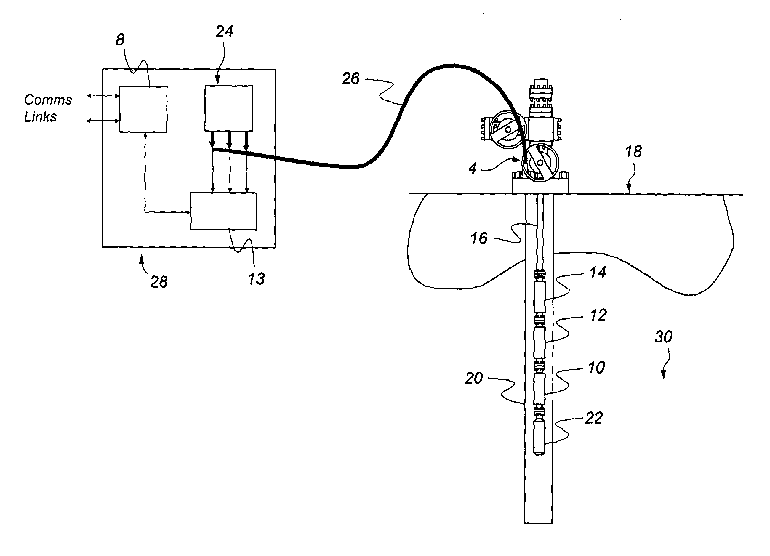
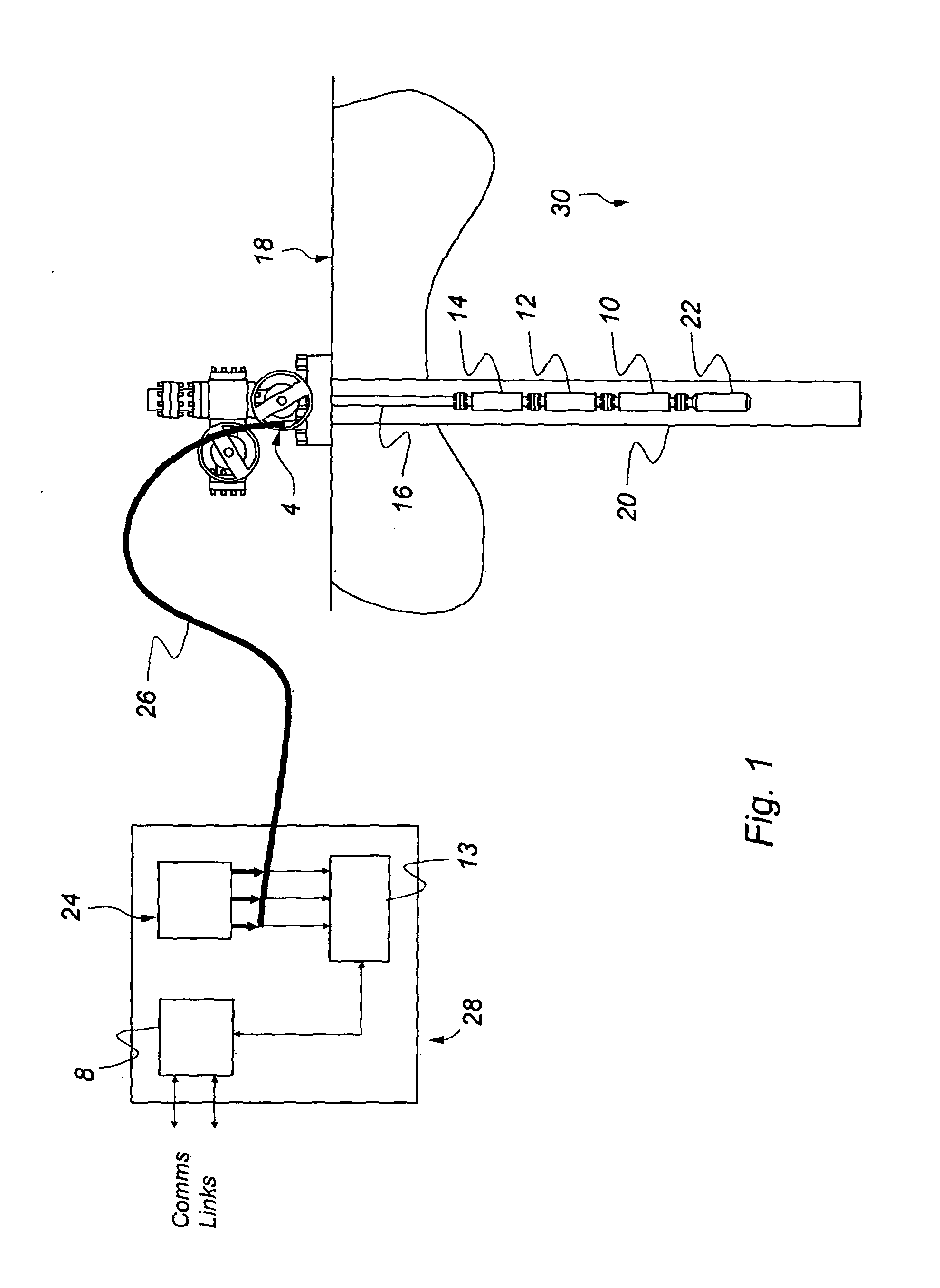
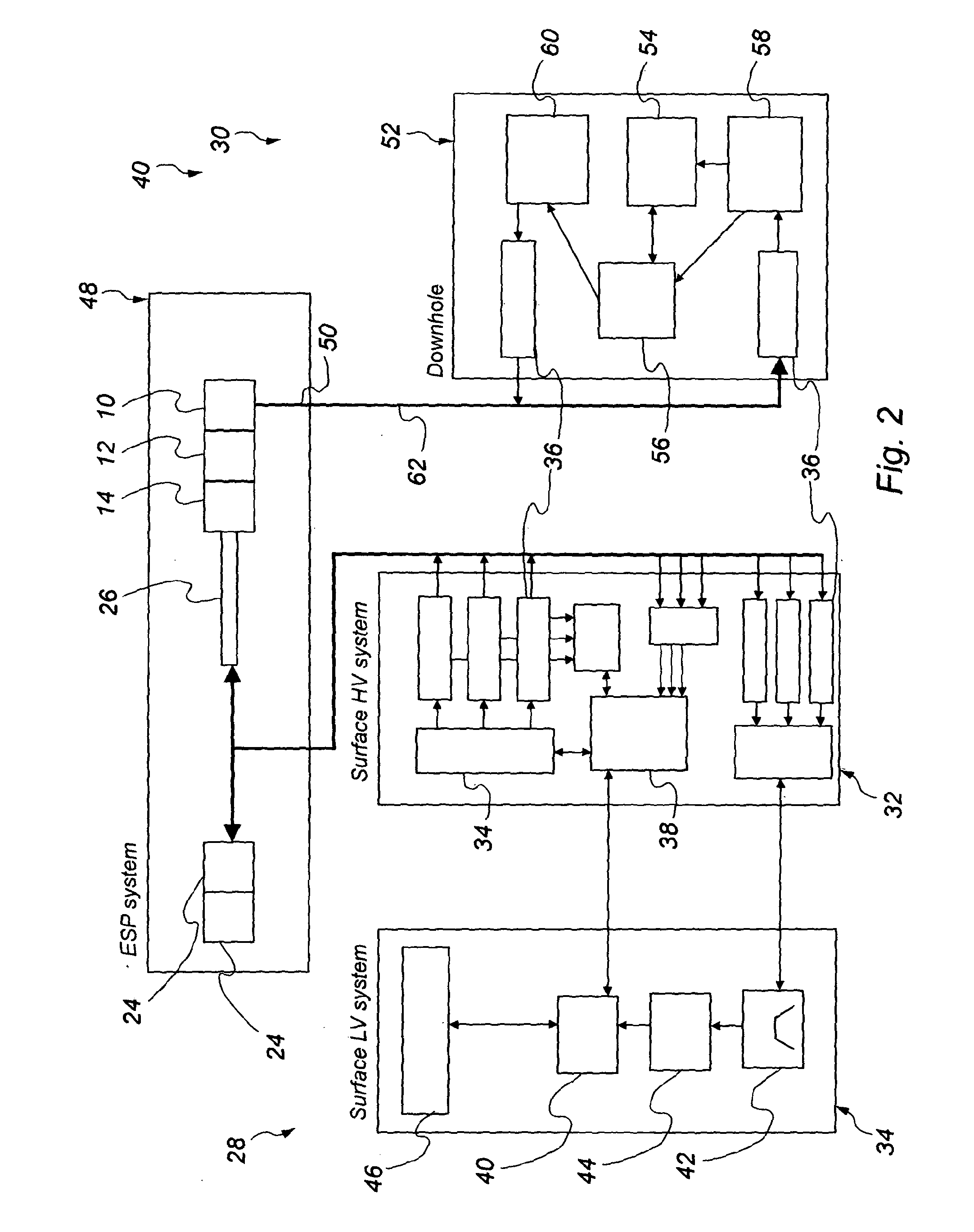
[0028]Reference is initially made to FIG. 1 of the drawings which illustrates a typical ESP completion in a wellbore. An ESP motor 10 is coupled through a seal 12 to a centrifugal pump 14 and used to lift the fluids through a tubing 16 to a surface 18 of the well 20 in a manner known to those skilled in the art. In order to monitor the operation, sensors or gauges 22 are located below the ESP 10. Typically, the motor 10 is a three phase Y configuration. The motor is driven by a variable speed drive system 24 and is connected via a three phase power cable 26. The system can be considered to comprise two distinct parts, a su...


PUM


Abstract

A method of high frequency data transmission for transmitting data over a three phase power system between a surface and a subsurface location, method using a first data transmit frequency and a second data transmit frequency, the data transmit frequencies being numerically distinct to each other and the data is transmitted on at least the second transmit frequency with a time delay between transmissions at each of the transmit frequencies to provide an uncorrupted data signal without interference. The invention finds specific application monitoring down hole equipment such as an electrical submersible pump in a wellbore.

Description

BACKGROUND OF THE INVENTION[0001]The present invention relates to data transmission to and from down hole equipment and in particular, though not exclusively, to an improved method of data transmission through a three phase power system between the sub surface and a surface location.[0002]“Down hole equipment” is understood to refer to any tool, equipment or instrument that is used in a wellbore.[0003]Data needs to be transmitted between down hole equipment and the surface for various purposes, for example: monitoring performance of motors / pumps; transmission of control signals for control of valves; measuring device orientation and position; and making physical measurements.[0004]For motorised down hole equipment, data needs to be sent from below the equipment in a circuit that includes motor windings and the equipment's power cable which can be considered as a three phase power system. The rationale is that since there are already power cables present the cost of the solution usin...

Claims


Application Information

Patent Timeline
Patent Type & Authority Applications(United States)
IPC IPC(8): H04B3/54E21B47/12
CPCH04B3/54E21B47/12E21B43/128H04B2203/5466H04B2203/5475
Inventor SHANKS, DAVID, SIRDA
Owner ZENITH OILFIELD TECHNOLOGY
Why Eureka
Try Eureka