Vehicle drive device

a technology for driving devices and vehicles, applied in vehicle sub-unit features, transportation and packaging, gearing, etc., can solve the problems of reducing affecting the mounting ability of the drive device on the vehicle, etc., to suppress the increase in the size of the entire drive device, secure the mountability of the vehicle drive device, and facilitate the connection

Active Publication Date: 2015-01-29
AISIN AW CO LTD +1
View PDF5 Cites 16 Cited by
  • Summary
  • Abstract
  • Description
  • Claims
  • Application Information

AI Technical Summary

Benefits of technology

[0018]According to the configuration, an opening portion in the axial direction can be formed on the opposite side of the rotary electric machine from the support wall side in the axial direction with the housing portion and the cover member removed from each other. Hence, the first wiring member which extends from the coil end portion on the cover member side (the opening portion side) and the first terminal of the terminal block can be easily connected to each other. In particular, the fourth terminal of the first wiring member and the first terminal of the ter

Problems solved by technology

In this case, a reduction in size of the entire drive device may be hindered if the electric wiring member are not appropriately routed to connect the control device which is external and the rotary electric machine and the rotation sensor disposed in the housing portion.
However, Patent Document 2 also does not describe a specific method to

Method used


Image

  • Vehicle drive device
  • Vehicle drive device
  • Vehicle drive device

Examples


Embodiment Construction

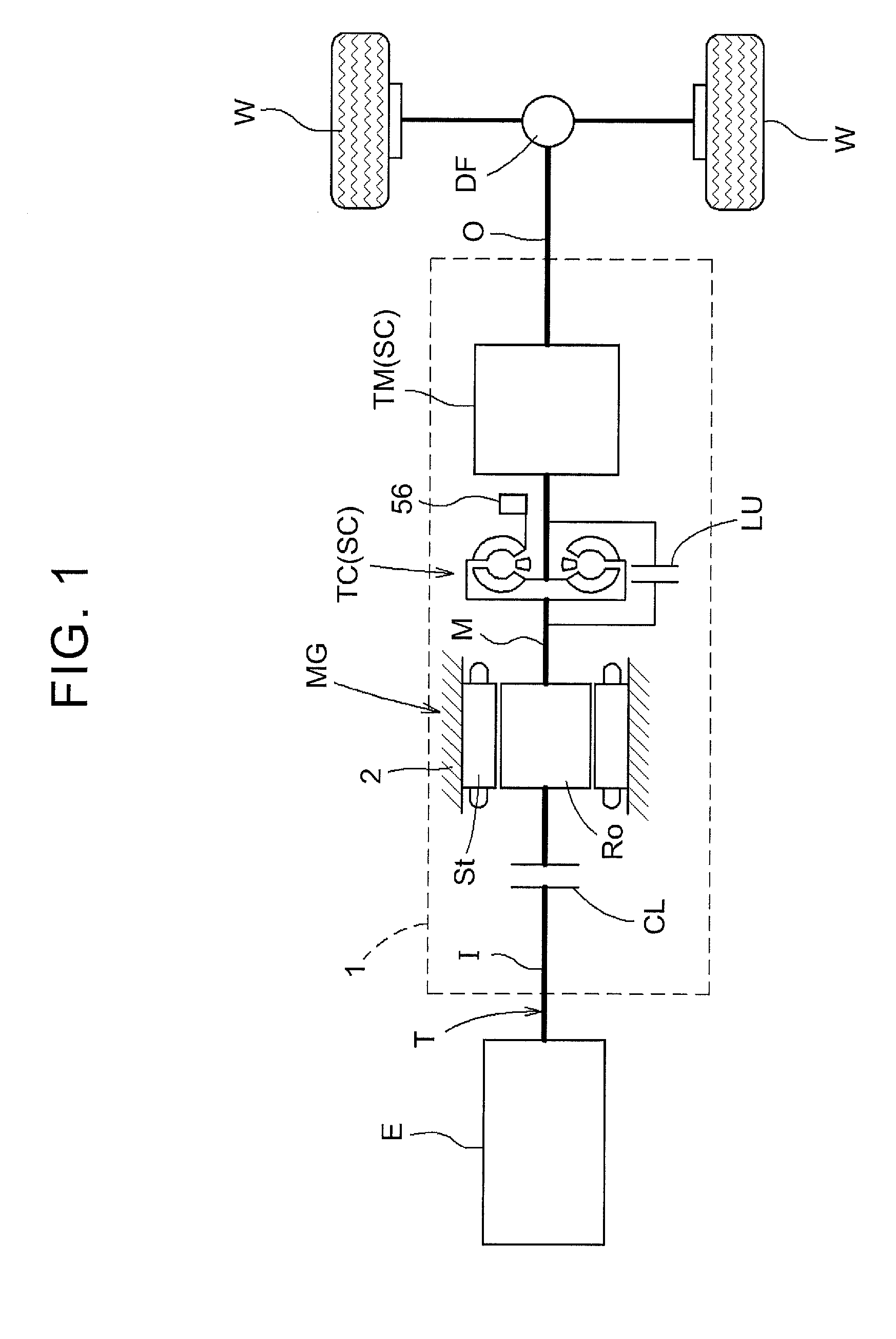
[0026]A vehicle drive device according to an embodiment of the present invention will be described with reference to the drawings. A vehicle drive device 1 according to the embodiment is a vehicle drive device (hybrid vehicle drive device) configured to drive a vehicle (hybrid vehicle) that includes both an internal combustion engine E and a rotary electric machine MG as drive force sources for wheels W. Specifically, the vehicle drive device 1 is constituted as a drive device for a one-motor parallel type hybrid vehicle.

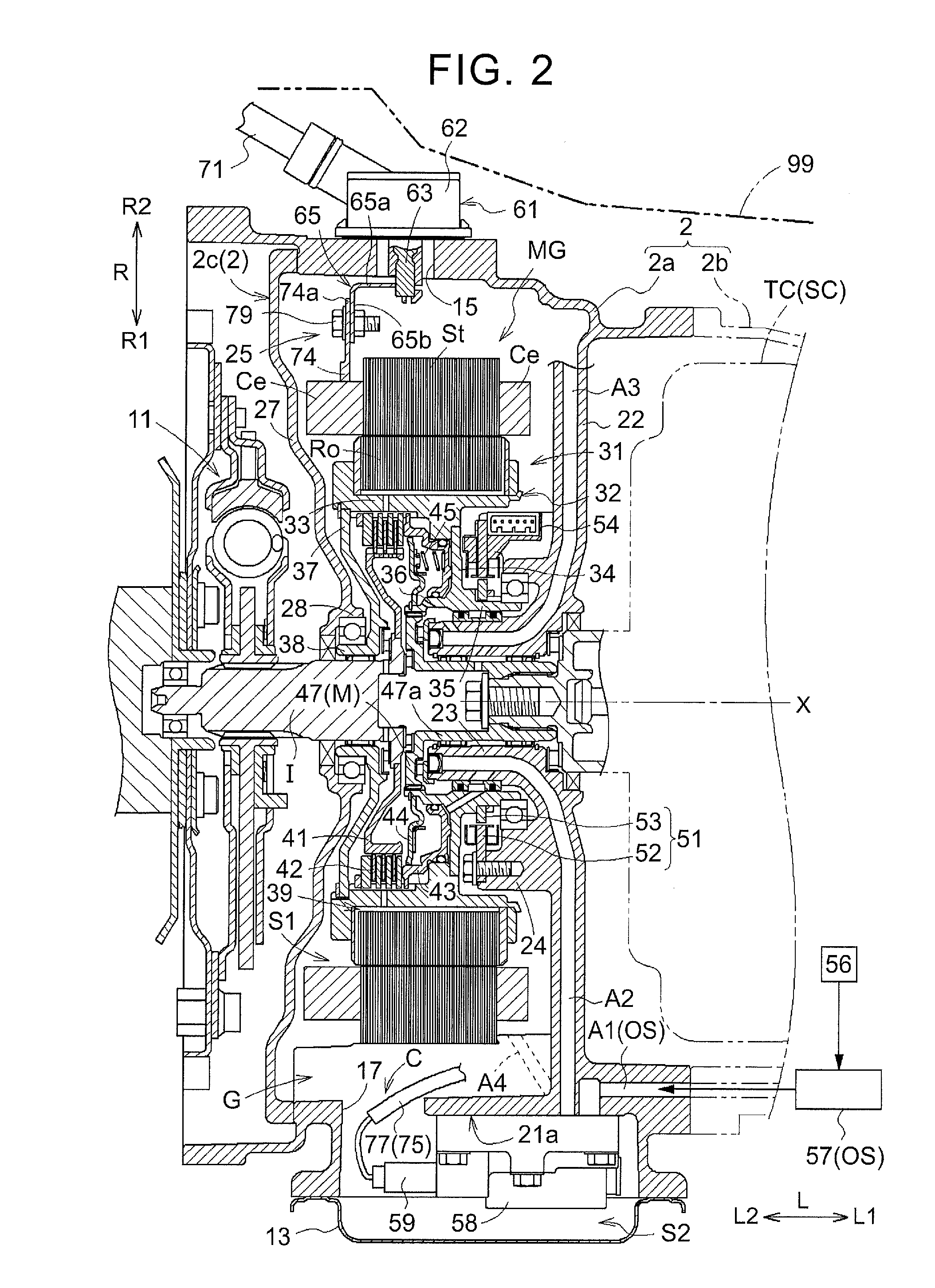
[0027]In the following description, unless specifically differentiated, the “axial direction L”, the “radial direction R”, and the “circumferential direction” are defined with reference to the rotational axis of the rotary electric machine MG (an axis X illustrated in FIG. 2). The “first axial direction L1” indicates the direction from a rotary electric machine MG side toward a speed change device SC along the axial direction L (toward the right in FIG. 2). The “sec...


PUM


Abstract

A vehicle drive device in which a friction engagement device, a rotary electric machine, and a speed change device are provided on a power transfer path that connects between an input member drivably coupled to an internal combustion engine and an output member drivably coupled to wheels, the elements provided in this order from the input member side. The disclosed combination achieves a variety of benefits, such as suppressing a steep rise in hydraulic pressure due to pressure discharged from a hydraulic control device, while maintaining a decreased size.

Description

TECHNICAL FIELD[0001]The present invention relates to a vehicle drive device in which a friction engagement device, a rotary electric machine, and a speed change device are provided on a power transfer path that connects between an input member drivably coupled to an internal combustion engine and an output member drivably coupled to wheels such that the friction engagement device, and the rotary electric machine, and the speed change device are arranged in this order from an input member side.BACKGROUND ART[0002]An example of the vehicle drive device described above is described in Japanese Patent Application Publication No, 2012-55039 (JP 2012-55039 A) (Patent Document 1). The device according to Patent Document 1 includes a rotary electric machine [electric motor 1] and a friction engagement device [clutch device 3] provided in a housing portion [motor cover 12] that has a support wall [fixed wall 111] disposed between the rotary electric machine and a speed change device [transm...

Claims


Application Information

Patent Timeline
IPC IPC(8): B60K6/405B60K6/54B60K6/387B60K6/48B60K6/26B60K6/36
CPCB60K6/405B60K6/26B60K6/54B60K6/387B60K6/48B60K6/36H02K5/225H02K7/006H02K9/19B60Y2400/426B60K6/547Y10T74/19056Y02T10/62
Inventor IWASE, MIKIOSUYAMA, DAIKIJINNAI, NAOYAOKISHIMA, TATSUYAWADA, KENSUKEINOUE, YUJIIDESHIO, YUKIHIKO
Owner AISIN AW CO LTD
Why Eureka
Try Eureka