Building and repair of hollow components

a hollow component and hollow technology, applied in the field of metal joining and additive manufacturing, can solve the problems of superalloy materials being among the most difficult materials to weld, the most difficult to weld, and the casting of a closed blade tip

Inactive Publication Date: 2015-02-05
SIEMENS ENERGY INC
View PDF2 Cites 70 Cited by
  • Summary
  • Abstract
  • Description
  • Claims
  • Application Information

AI Technical Summary

Problems solved by technology

Superalloy materials are among the most difficult materials to weld due to their susceptibility to weld solidification cracking and strain age cracking.
Within the zone of non-weldability, the alloys with the highest aluminum content are generally found to be the most difficult to weld.
However, such fixturing prevents casting of a closed blade tip in the primary casting process.

Method used


Image

  • Building and repair of hollow components
  • Building and repair of hollow components
  • Building and repair of hollow components

Examples


Embodiment Construction

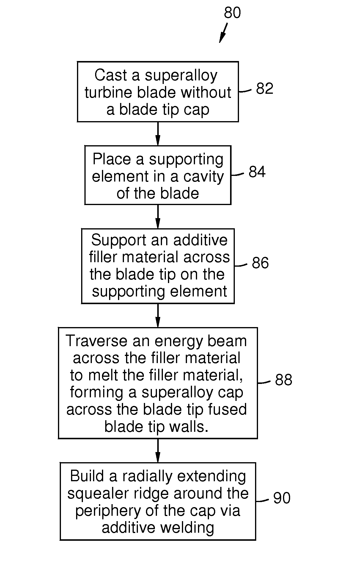
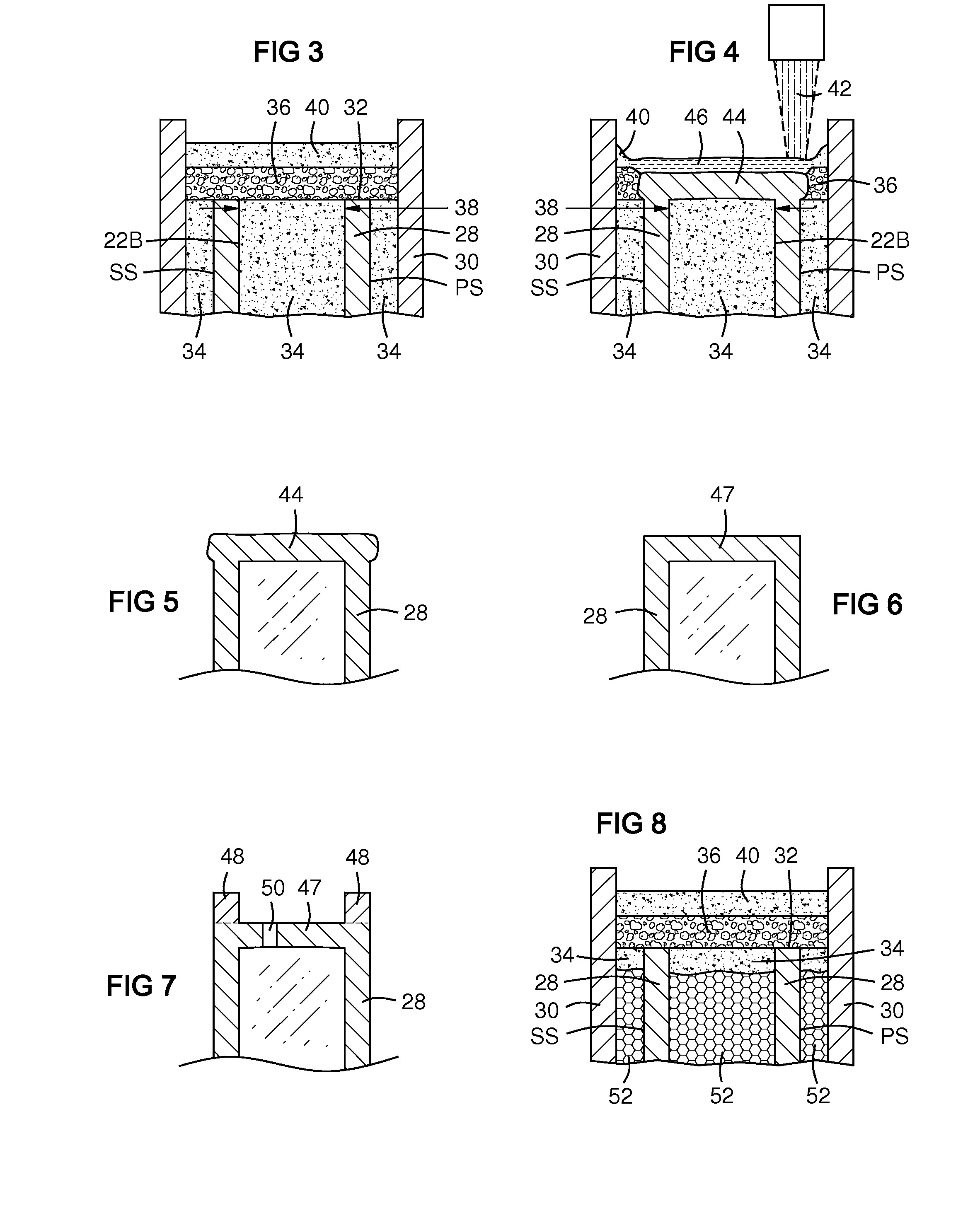
[0024]The present inventors have created a process of building a tip cap on a hollow superalloy turbine blade or closing another opening in a component by supporting a filler material across the opening on a supporting element in a cavity of the component, and then traversing the filler material with an energy beam to melt it, forming a deposit across the opening fused to the edges of the opening. The filler material may be a powder that includes metal and may further include flux. It is supported across the opening by a fugitive supporting element behind the opening. “Fugitive” means removable after melting and cooling of the metal, for example by a mechanical process, by fluid flushing, by chemical leaching and / or by any other known process capable of removing the fugitive material from its position. The supporting element may be a powder and / or other form of material disposed in a cavity behind the opening. Examples include additional filler powder and / or flux or ceramic powder. ...


PUM

PropertyMeasurementUnit
thicknessaaaaaaaaaa
heataaaaaaaaaa
energyaaaaaaaaaa

Abstract

A method of building or repair of a hollow superalloy component (20, 61) by forming an opening (38, 62) in a wall (28) of the component; filling a cavity (22B, 64) behind the opening with a fugitive support material (34, 52, 54, 68) to support a filler powder (36) across the opening; traversing an energy beam (42) across the filler powder to form a deposit (44) that spans and closes the opening; in which the deposit is fused to the edges (32, 62) of the opening. The filler powder includes at least metal, and may further include flux. The support material may include filler powder, a solid (54), a foam (52) insert, a flux powder (34) and/or other ceramic powder (68). Supporting powder may have a mesh size smaller than that of the filler powder.

Description

[0001]This application is a continuation-in-part of U.S. patent application Ser. No. 13 / 956,635, filed 1 Aug. 2013, attorney docket number 2013P12505US, which is incorporated by reference herein.FIELD OF THE INVENTION[0002]This invention relates generally to the fields of metals joining and additive manufacturing and, more particularly, to a process for depositing metal using a laser heat source.BACKGROUND OF THE INVENTION[0003]Superalloy materials are among the most difficult materials to weld due to their susceptibility to weld solidification cracking and strain age cracking. The term “superalloy” as used herein means a highly corrosion and oxidation resistant alloy with excellent mechanical strength and resistance to creep at high temperatures. Superalloys typically include high nickel or cobalt content. Examples of superalloys include alloys sold under the trademarks and brand names Hastelloy, Inconel alloys (e.g., IN 738, IN 792, IN 939), Rene alloys (e.g., Rene N5, Rene 80, Re...

Claims


Application Information

Patent Timeline
Patent Type & Authority Applications(United States)
IPC IPC(8): B23P6/00B22D19/10B23K26/34B22D23/06
CPCB23P6/007B23K26/345B22D19/10B22D23/06F01D5/005B22F2007/068B23P2700/06F01D5/20F05D2230/22F05D2240/307B23K26/342B23K2101/001Y02P10/25B22F10/47
Inventor BRUCK, GERALD J.KAMEL, AHMED
Owner SIEMENS ENERGY INC
Why Eureka
Try Eureka