
Method for producing a diffraction grating

a technology of diffraction grating and grating plate, which is applied in the field of diffraction optics, can solve the problems of gratings that suffer, no light in the angular direction, and destructive interference in other directions, and achieve the effect of convenient manufacture and beneficial stray light characteristics

Active Publication Date: 2015-02-05
STICHTING NEDERLANDSE WETENSCHAPPELIJK ONDERZOEK INSTN +1
View PDF8 Cites 28 Cited by
  • Summary
  • Abstract
  • Description
  • Claims
  • Application Information

AI Technical Summary

Benefits of technology

The method described in this patent allows for the easy creation of diffraction gratings with controlled efficiency. This is accomplished by calculating the desired corrugation amplitude based on the desired diffraction efficiency, and then manufacturing the grating with that desired corrugation amplitude using control of an anisotropic etching process. The method ensures that the grating is efficient in diffracting light.

Problems solved by technology

A diffraction grating operates on the principle that phases of light traveling through different light paths, reflected or transmitted by the grating lines, constructively interfere in certain directions while destructively interfering in other directions.
There is virtually no light in the angular directions between these orders since the contributions interfere here destructively.
Ruled gratings typically suffer from “Rowland ghosts”, generated by the presence of several line densities on the same grating.
Disadvantageously, ruled gratings are limited by the size and shape of the ruling tip and the precision of the ruling instrument.
However, this improvement may be insubstantial on the overall scheme of efficiency improvements, in particular for a grating operation regime of interest as exemplified in the present disclosure.

Method used


Image

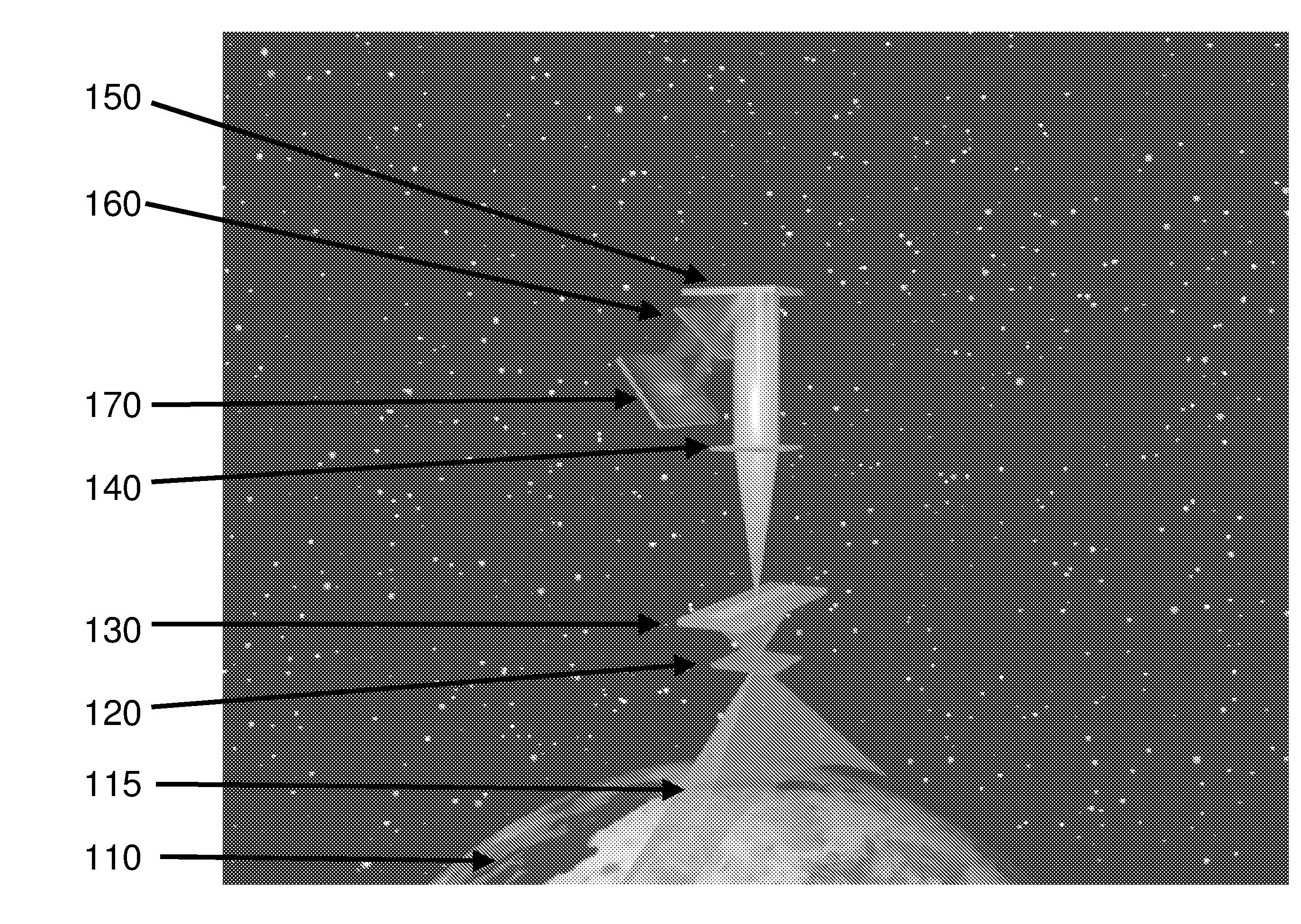
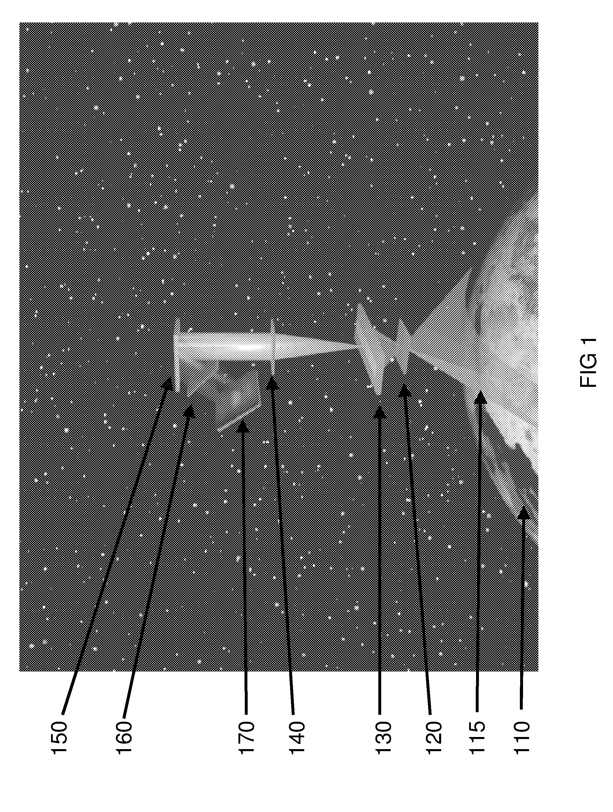
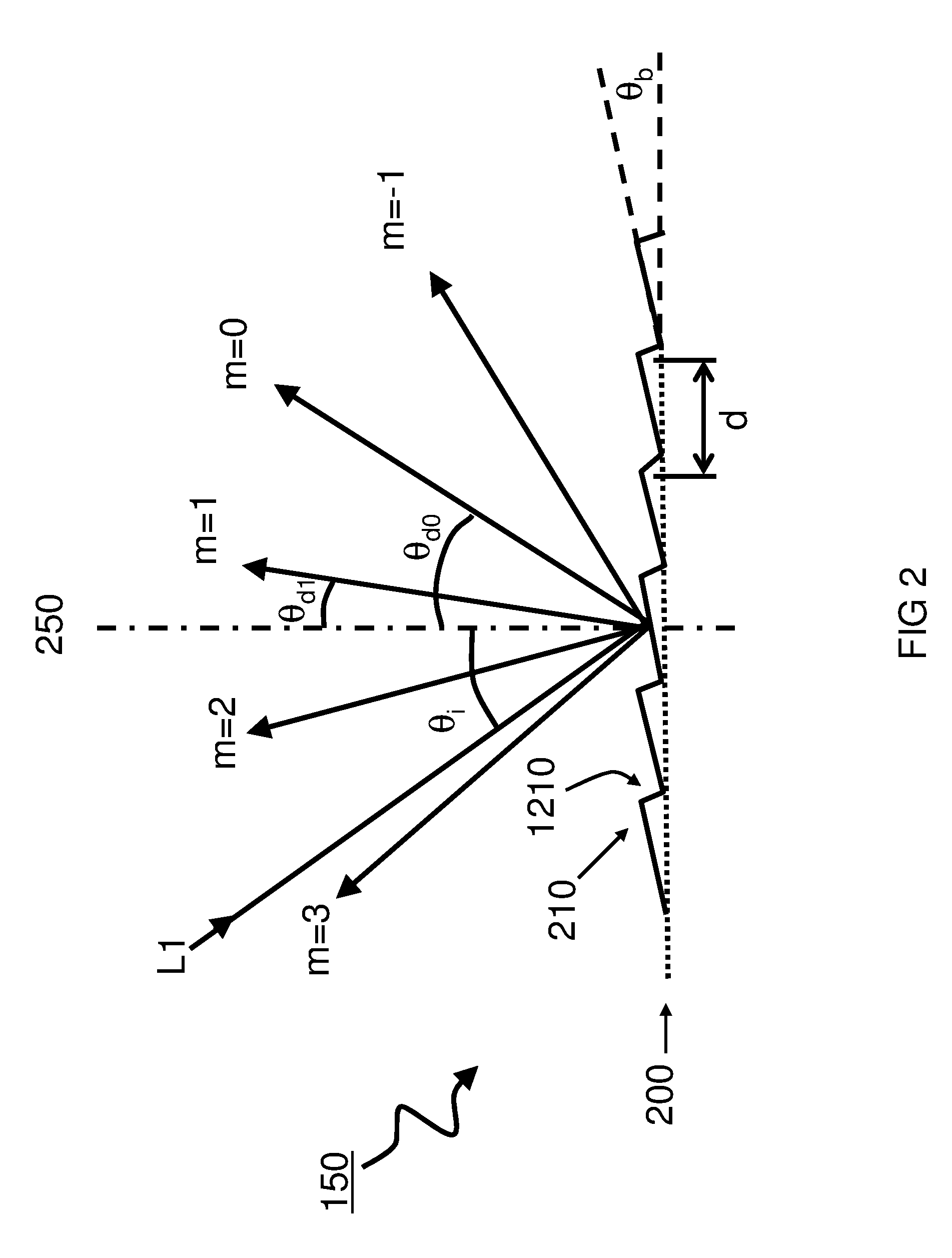
  • Method for producing a diffraction grating
  • Method for producing a diffraction grating
  • Method for producing a diffraction grating

Examples


Embodiment Construction

[0042]The following description of certain exemplary embodiments is merely exemplary in nature and is in no way intended to limit the invention, its application, or uses. In the following detailed description of embodiments of the present systems, devices and methods, reference is made to the accompanying drawings which form a part hereof, and in which are shown by way of illustration specific embodiments in which the described devices and methods may be practiced. These embodiments are described in sufficient detail to enable those skilled in the art to practice the presently disclosed systems and methods, and it is to be understood that other embodiments may be utilized and that structural and logical changes may be made without departing from the spirit and scope of the present system. The following detailed description is therefore not to be taken in a limiting sense, and the scope of the present system is defined only by the appended claims. Moreover, for the purpose of clarity...


PUM


Abstract

A manufacturing method for a grating is disclosed for the angular dispersion of light impinging the grating. The grating comprises tapered structures and cavities. A cavity width and / or corrugation amplitude is varied for achieving a desired grating efficiency according to calculation. A method is disclosed for conveniently creating gratings with variable cavity width and / or corrugation amplitude. The method comprises the step of anisotropically etching a groove pattern into a grating master. Optionally a replica is produced that is complementary to the grating master. By variation of an etching resist pattern, the cavity width of the grating may be varied allowing the optimization towards different efficiency goals.

Description

FIELD AND BACKGROUND OF THE INVENTION[0001]The present invention relates to the field of diffraction optics, in particular to the design, production, and use of high efficiency diffraction gratings.[0002]The term “grating” refers to a periodic or semi-periodic array of lines on a surface. A diffraction grating operates on the principle that phases of light traveling through different light paths, reflected or transmitted by the grating lines, constructively interfere in certain directions while destructively interfering in other directions. The angular directions with constructive interference form the so called diffraction orders and are known to depend on wavelength of the light and pitch of the grating. There is virtually no light in the angular directions between these orders since the contributions interfere here destructively. Such gratings have various uses in the field of optics.[0003]Diffraction gratings are used e.g. in spectrographs to provide angular dispersion of light....

Claims


Application Information

Patent Timeline
IPC IPC(8): G02B27/42G02B5/18H01S3/08H01S3/092H01S3/0933G01J3/18H01S3/16
CPCG02B27/4244G01J3/18G02B5/1866G02B5/1857H01S3/08009H01S3/1636H01S3/092H01S3/0933G02B5/1852G02B5/008G02B5/1828G01J3/1804G01J3/24
Inventor VINK, HENRI JOHANNES PETRUSVISSER, HUIBERTVAN AMERONGEN, AALDERT HIDE
Owner STICHTING NEDERLANDSE WETENSCHAPPELIJK ONDERZOEK INSTN
Learn More