Ammonia slip catalyst

a technology of ammonia slip and catalyst, which is applied in the field of oxidation catalyst, can solve the problems of undesirable unreacted ammonia that passes through the scr process, particularly problematic, and achieves the effects of reducing ammonia slip, increasing the co and hc oxidative potential of the catalyst, and little or no increase in secondary nox

Active Publication Date: 2015-02-05
JOHNSON MATTHEY PLC
View PDF31 Cites 95 Cited by
  • Summary
  • Abstract
  • Description
  • Claims
  • Application Information

AI Technical Summary

Benefits of technology

[0011]The present invention, in part, pertains to a heterogeneous oxidation catalyst that is particularly effective at concurrently reducing ammonia slip without significant NOx formation and oxidizing CO and HC. Surprisingly, the inclusion of palladium in the top layer of a bi-layer or tri-layer ASC increases the CO and HC oxidative potential of the catalyst while producing little or no increase in secondary NOx from the oxidation of NH3. This result is particularly surprising since Pd is known to be a powerful NH3 oxidation catalyst. In the present catalyst, a majority of the NH3 passes through the Pd-layer to a lower layer where it is oxidized.

Problems solved by technology

The reduction of NOx to N2 is particularly problematic in lean burn exhaust gas because the exhaust gas contains enough oxygen to favor oxidative reactions instead of reduction.
Unreacted ammonia that passes through the SCR process (also referred to as “ammonia slip”) is undesirable, because the slipped ammonia gas can react with other combustion species and / or negatively impact the atmosphere if released.

Method used


Image

  • Ammonia slip catalyst
  • Ammonia slip catalyst
  • Ammonia slip catalyst

Examples


example 1

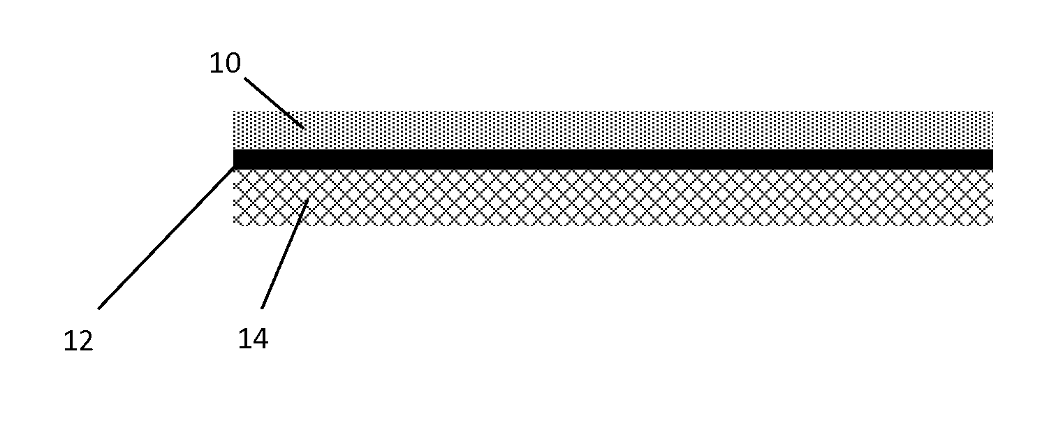
Preparation of ASC Catalysts Having Pd in Top Layer

[0082]A flow-through honeycomb core (4.66 inches by 3.0 inches, 400 cpsi, 4 mil wall thickness) was coated with a first oxidation catalyst to form a bottom layer and then coated with a second oxidation catalyst / SCR catalyst to form a top layer over the bottom layer.

[0083]The catalyst of the bottom layers were prepared as follows: Add milled gamma alumina washcoat to an appropriate container. The d50 of the gamma alumina was determined to be about 3.2-4.0 μm. Deionized water was mixed into the washcoat using a high shear mixer and succinic acid was added to the washcoat to form a gel. Various amounts of platinum nitrate and optionally palladium nitrate were added to the gel and then the material was mixed to form a slurry. The slurry was applied to the honeycomb core as a bottom catalyst layer and the coated core was dried and calcined. The various amounts of Pt and Pd in the samples are show in Table 1.

[0084]The catalysts of the top...

example 2

Catalyst Performance

[0086]A catalyst sample having a top layer containing a mixture of a vanadium-based SCR catalyst and a Pd oxidation catalyst and a bottom layer containing Pt AMOX catalyst was evaluated for NH3 conversion, CO conversion, and HC conversion. These results were compared to a similar catalyst, but without the Pd oxidation catalyst in the top layer. The catalyst having Pd in the top layer shows significantly better CO and HC conversion performance compared to the catalyst without Pd in the top layer (FIGS. 3 and 4). Surprisingly, the catalyst prepared with and without the Pd top layer show very similar performance in terms of NH3 conversion and NOx outlet. (FIG. 5)

[0087]A catalyst sample having a top layer containing a mixture of a Cu / SAPO-34 SCR catalyst and a Pd oxidation catalyst and a bottom layer containing Pt AMOX catalyst was evaluated for N2 selectivity for NH3 conversion over a wide range of temperatures and also for CO conversion. These results were compared...


PUM

PropertyMeasurementUnit
porosityaaaaaaaaaa
combustion temperaturesaaaaaaaaaa
chemical equationaaaaaaaaaa

Abstract

Provided is an ammonia slip catalyst article having supported palladium in a top or upstream layer for oxidation of carbon monoxide and/or hydrocarbons, an SCR catalyst either in the top layer or in a separate lower or downstream layer, and an ammonia oxidation catalyst in a bottom layer. Also provided are methods for treating an exhaust gas using the catalyst article, wherein the treatment involves reducing the concentrations of ammonia and optionally carbon monoxide and/or hydrocarbons in the exhaust gas.

Description

CROSS-REFERENCE TO RELATED APPLICATIONS[0001]This application claims priority benefit to U.S. Provisional Patent Application No. 61 / 859,993 filed on Jul. 30, 2013, which is incorporated herein by reference.BACKGROUND[0002]1. Field of Invention[0003]Provided is an oxidation catalyst for treating combustion exhaust gas, and particularly for reducing ammonia slip associated with a selective catalytic reduction process.[0004]2. Description of Related Art[0005]Combustion of hydrocarbon fuel produces engine exhaust or flue gas that contains, in large part, relatively benign nitrogen (N2), water vapor (H2O), and carbon dioxide (CO2). But the exhaust gases also contains, in relatively small part, noxious and / or toxic substances, such as carbon monoxide (CO) from incomplete combustion, hydrocarbons (HC) from un-burnt fuel, nitrogen oxides (NOx) from excessive combustion temperatures, and particulate matter (mostly soot). To mitigate the environmental impact of exhaust gas released into the a...

Claims


Application Information

Patent Timeline
Patent Type & Authority Applications(United States)
IPC IPC(8): B01J29/85B01D53/86B01J23/44
CPCB01J29/85B01D53/869B01D53/8628B01J23/44B01J23/72B01J23/745B01J35/0006B01J35/04B01J37/0244B01J37/0246B01J37/0248B01D46/2429B01D46/24491B01D46/2476F01N3/10F01N2570/12B01D53/9418B01D53/9468B01D2255/911B01D2255/9022B01D2255/1023B01D2255/50B01D2255/20738B01D2255/20761B01D2255/1021B01D2255/9025B01J29/072Y02A50/20B01D53/9472F01N3/2066B01J35/00B01J37/02B01D53/94B01D2255/902B01J2523/842B01J2523/17B01J23/38B60K13/04B01D53/9477B01D2255/904B01D2255/9155B01J23/6482
Inventor FEDEYKO, JOSEPH MICHAELDOURA, KEVINWEIGERT, ERICH CONLANCOX, JULIAN PETERCHEN, HAI-YINGANDERSEN, PAUL JOSEPH
Owner JOHNSON MATTHEY PLC
Why Eureka
Try Eureka