Exhaust gas mixer and system

a technology of exhaust gas mixer and exhaust gas, which is applied in the direction of machines/engines, engine components, mechanical equipment, etc., can solve the problems of not providing a sample of exhaust, poor soot distribution, etc., and achieve the effect of improving flow mixing, accurate reading, and improving performan

Inactive Publication Date: 2015-02-19
FORD GLOBAL TECH LLC
View PDF7 Cites 17 Cited by
  • Summary
  • Abstract
  • Description
  • Claims
  • Application Information

AI Technical Summary

Benefits of technology

[0006]The inventors herein provide a system including a perforated barrier disposed within an exhaust stream downstream from the engine cylinder(s). The perforated barrier may divide the exhaust stream radially and longitudinally. The system may also include a mixing surface coupled with the perforated barrier. The mixing surface may define a path within the exhaust stream to impart a swirl to the exhaust stream. In this way, any soot that may be in the exhaust stream may be better mixed into the exhaust stream to provide a more homogeneous mixture. In this way, the soot sensor may provide a more accurate reading of the amount of soot that may be present in the exhaust stream. Using both flow impingement and swirling together may tend to improve flow mixing, and may provide improved performance with less pressure loss.
[0007]The perforated barrier may have a circumferential edge in substantial sealing engagement with an inner diameter wall of an exhaust conduit. The barrier may define a surface which extends upstream from the circumferential edge while extending in a radial direction from the inner diameter wall. In this way, as exhaust gas flows across the barrier it may enter a region between the circumferential edge of the exhaust conduit and the barrier outer surface. The barrier may divide the exhaust conduit into two parts, and consequently two exhaust flow paths, an upstream path and a downstream path. Flow in upstream path may pass through the perforated holes on the perforated barrier to exit to the downstream path. Since the perforated holes may be located at circumference of the barrier surface, the flow direction may be significantly pointed toward the center line of exhaust conduit. The mixing surface coupled with the perforated barrier may create a swirling flow. As flow enters the region between exhaust conduit and cone outer surface area, it may follow the curve of the mixing surface and flow rotation may be generated before it passes through the perforated holes. As the flow exits from perforated holes, the swirling momentum may carry on inside the perforated barrier and help flow mixing. With those two flow mechanisms, soot particulates may be more uniformly distributed downstream of the perforated barrier forming an effective soot mixer. In this way, the soot sensor can detect soot leakage within short distance from the DPF.
[0008]Embodiments may provide a system including a conduit for passing a stream of exhaust from a combustion chamber of an internal combustion engine. An exhaust gas sensor may be located within the conduit. A wall may be located within the conduit upstream from the exhaust gas sensor. The shape of the wall may at least approximate a cone and may have an upstream portion with a first outer diameter and a downstream portion with a second outer diameter. The second outer diameter may be larger than the first outer diameter. A plurality of passages may be in the wall. One or more edges may be coupled with the wall and may extending axially and radially within the conduit. In this way the edges may impart at least a partial swirl to the flow of exhaust, and the configuration of the wall and the plurality of passages may tend to intermix relatively upstream exhaust with relatively downstream exhaust. In this way the exhaust may be more thoroughly mixed even a relatively short distance from the DPF.
[0009]Various embodiments may provide a system including a circular exhaust pipe having a perforated bell housing with an open end of the bell facing downstream. A plurality of fins may extend helically around an outer surface of the perforated bell. In this way, soot that may be present in the exhaust stream may be more homogenously mixed into the exhaust stream which may provide a more accurate exhaust sample to be sensed by the soot sensor.

Problems solved by technology

For example many DPF cracks may originate close to the DPF circumference area of the exhaust conduit.
In addition, many applications require that the on board diagnostic soot sensor be located a short distance downstream from the DPF exit cone where soot distribution is usually very poor due to a lack of distance for adequate soot particulates redistribution.
The disclosed attempt does not, however, provide a sample of exhaust which better represents the overall concentration of soot in the exhaust stream.

Method used


Image

  • Exhaust gas mixer and system
  • Exhaust gas mixer and system
  • Exhaust gas mixer and system

Examples


Embodiment Construction

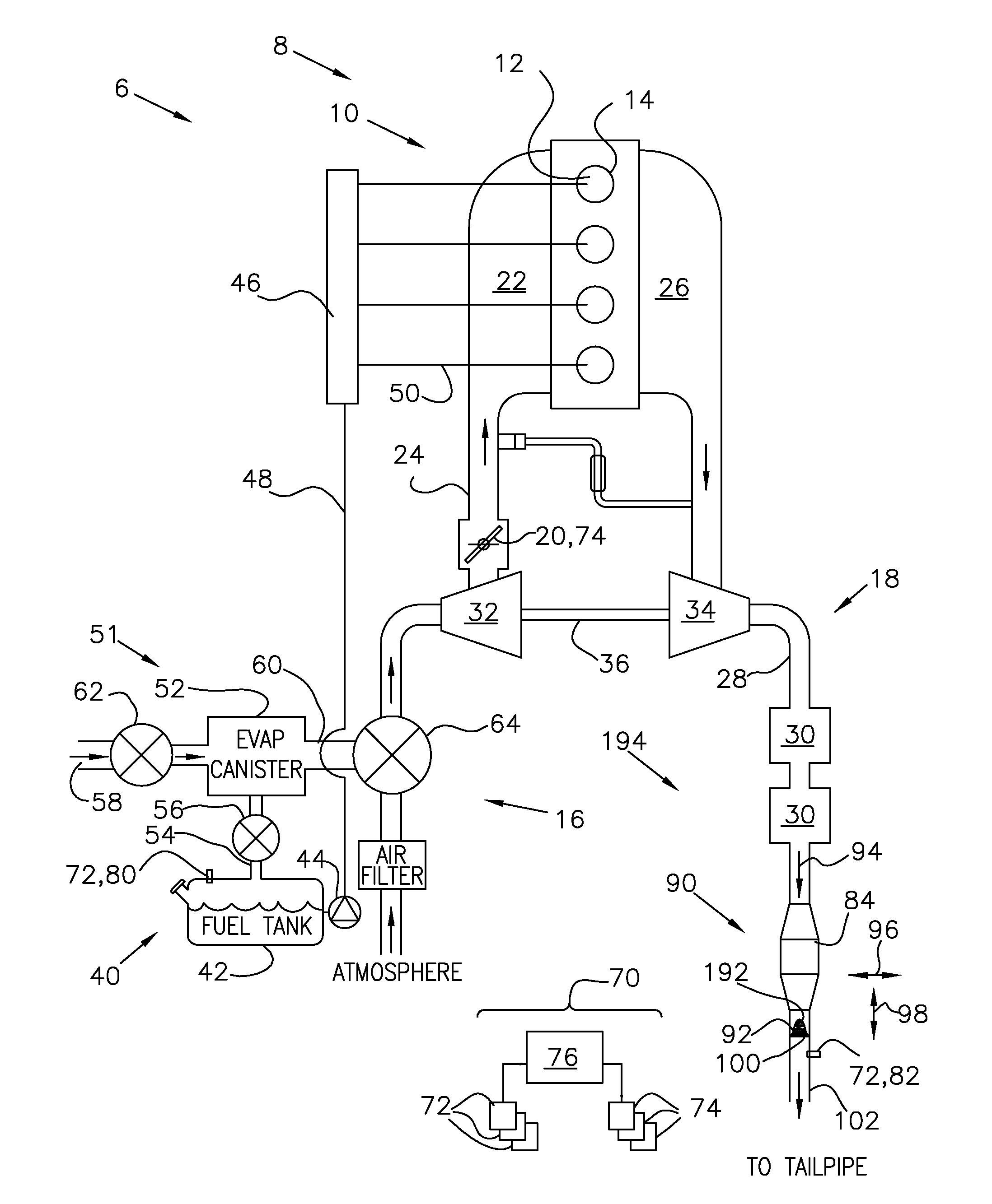
[0017]FIG. 1 shows a schematic depiction of a vehicle system 6. The vehicle system 6 includes an engine system 8. The engine system 8 may include an engine 10 having a plurality of cylinders 12 defining a respective plurality of combustion chambers 14. The engine 10 may include an engine intake 16 and an engine exhaust 18. The engine intake 16 may include a throttle 20 fluidly coupled to an engine intake manifold 22 via an intake passage 24 to regular intake air flow. The engine exhaust 18 may include an exhaust manifold 26 leading to an exhaust passage 28 that routes exhaust gas to the atmosphere via a tailpipe. The engine exhaust 18 may include one or more emission control devices 30, which may be mounted in a close-coupled position in the exhaust. The one or more emission control devices may include a three-way catalyst, lean NOx trap, diesel particulate filter, oxidation catalyst, etc. It will be appreciated that other components may be included in the engine such as a variety o...


PUM


Abstract

A device and a system are provided. The system may include a perforated barrier disposed within an exhaust stream downstream from the combustion chamber(s). The barrier may divide the exhaust stream radially and longitudinally. A mixing surface may be coupled with the perforated barrier which may define a path within the exhaust stream to impart a swirl to the exhaust stream.

Description

TECHNICAL FIELD[0001]The present application relates to a device and a system for mixing exhaust gas having a perforated wall and one or more surfaces to impart at least a partial swirl to an exhaust flow.BACKGROUND AND SUMMARY[0002]A diesel particulate filter (DPF) may be used to remove diesel particulate matter or soot from the exhaust gas of a diesel engine. A soot sensor may be located downstream from the DPF and may be configured to determine whether or not a soot concentration in the exhaust gas is within acceptable levels.[0003]The inventors herein have recognized examples wherein the soot sensor reading may not represent the actual average soot concentration. For example many DPF cracks may originate close to the DPF circumference area of the exhaust conduit. Accordingly, the concentration of soot closer to the conduit center may be lower than average levels, and higher than average levels at near the conduit circumference. In addition, many applications require that the on ...

Claims


Application Information

Patent Timeline
Patent Type & Authority Applications(United States)
IPC IPC(8): F01N3/02
CPCF01N3/02F01N3/28F01N13/20F01N2240/20Y02T10/40
Inventor ZHANG, XIAOGANG
Owner FORD GLOBAL TECH LLC
Why Eureka
Try Eureka