Smartphone based passive keyless entry system

Inactive Publication Date: 2015-02-19
DIRECTED
View PDF4 Cites 183 Cited by
  • Summary
  • Abstract
  • Description
  • Claims
  • Application Information

AI Technical Summary

Benefits of technology

[0009]In order to overcome the limitations of the prior art, provided is a passive keyless system and a method for setting the distance and conditions for triggering the lock mechanism of an access area. In the current invention, disclosed is a method of using standard Bluetooth RSSI or other RF power indication protocols to program or set the distance for the lock and unlock of an access point in a passive keyless entry system. It is an objected of the present invention to provide a passive keyless entry system that allows the user to program or set, using a simple user interface, the distance that passive triggering of the lock

Problems solved by technology

One problem with such a system is that the signal detection range can vary greatly from system to system, especially in aftermarket applications where environmental and installation factors can vary greatly.
This causes locking and unlocking at a distance that is inconsistent and may not be desired in certain context.
Another problem is that constant transmission by the handheld unit quickly drains the battery life, requiring constant recharging or battery replacement.
If the user fails to recharge, access to the vehicle will not be allowed because a signal is no longer transmitted.
Additionally, these systems tend to trigger a locking mechanism to lock and unlock each time a user crosses the threshold of the distance set for the detection system.
Thus, in a poorly configured system, a door might well unlock when the user is within the detection range, whether or not the user intended it.
If the vehicle is not regularly driven, this type of system may drain the vehicle battery, not only preventing access to the vehicle, but also preventing start of the engine.
Additionally, transponder based systems are limited in that they typically operate at 125 KHZ, with resulting low range.
While these low frequency systems res

Method used


Image

  • Smartphone based passive keyless entry system
  • Smartphone based passive keyless entry system
  • Smartphone based passive keyless entry system

Examples


Embodiment Construction

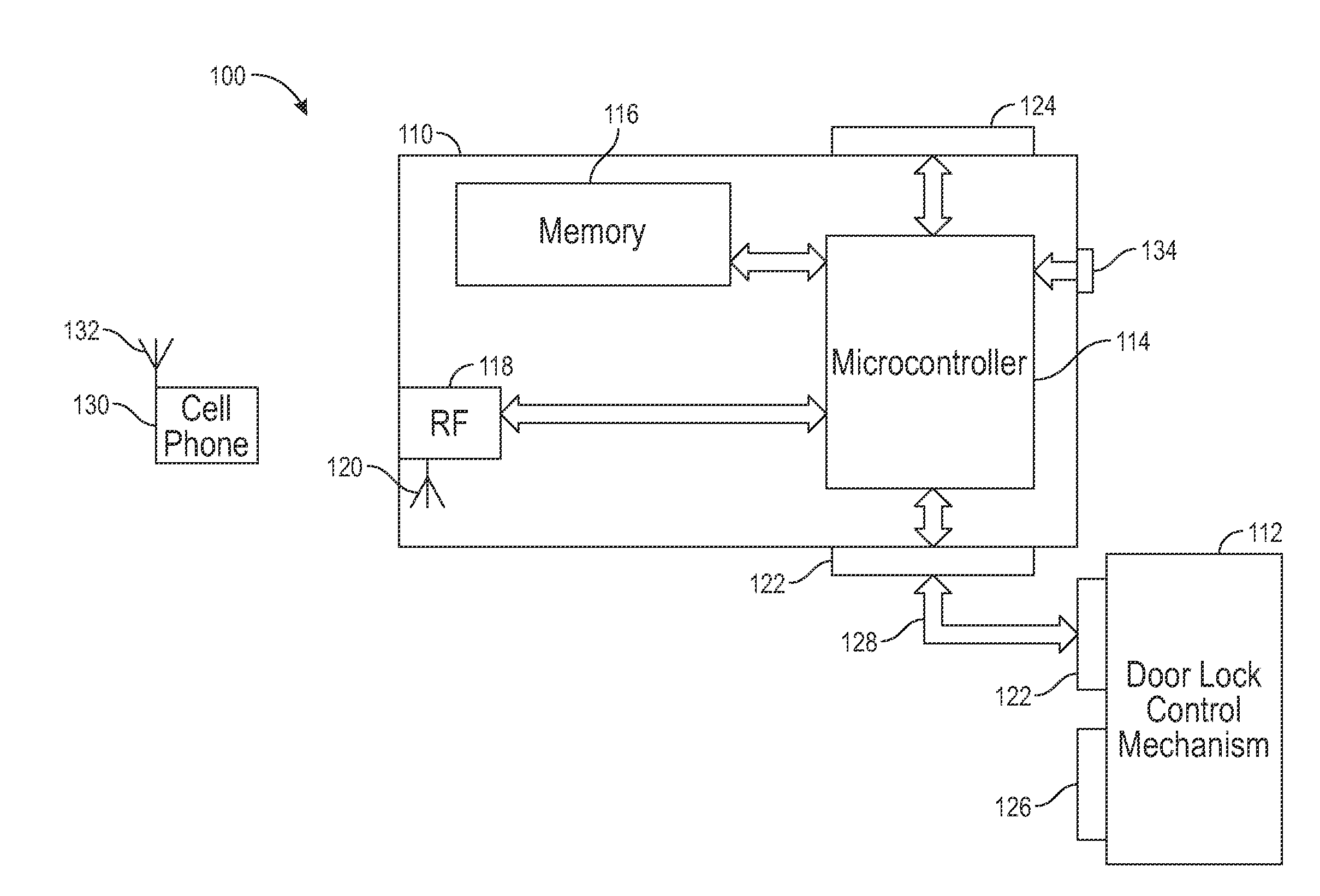
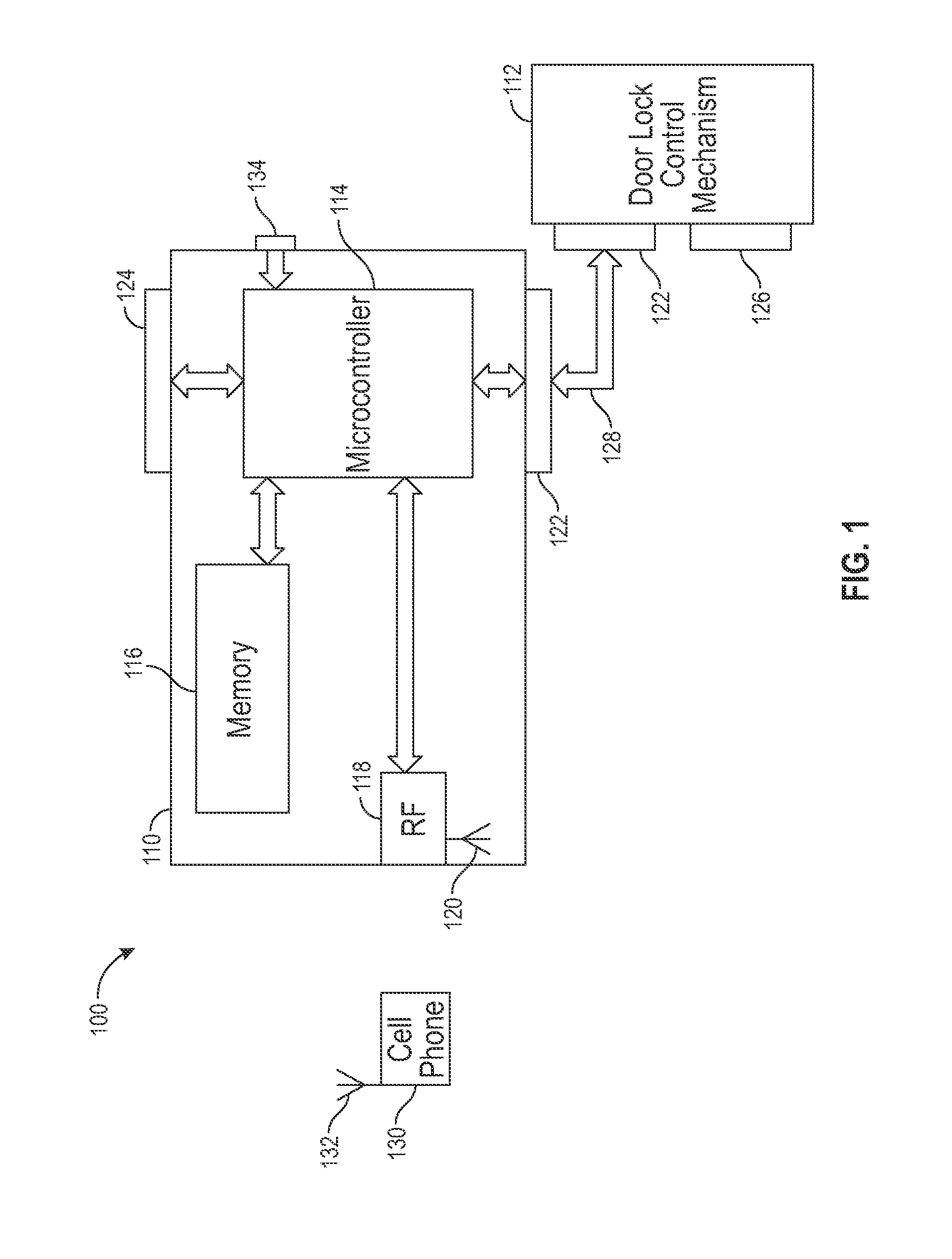
[0014]The present invention provides for a passive keyless entry system and method that provides for setting the distance and conditions for triggering a lock mechanism using a short range RF enabled smart phone paired with an enabled transceiver module installed in a vehicle, building or other secured access point. Example embodiments are described herein. Those of ordinary skill in the art will realize that the following descriptions are illustrative only and are not intended to be in any way limiting. Other embodiments will readily suggest themselves to such skilled persons having the benefit of this disclosure. Reference will now be made in detail to implementations of the example embodiments as illustrated in the accompanying drawings. The same reference indicators may be used throughout the drawings and will refer to the same or like items.

[0015]Now with reference to the various figures, FIG. 1, is an exemplary embodiment of the inventive subject matter providing a passive key...


PUM


Abstract

A passive keyless entry system is provided comprising an access point module, a smart phone for capable of transmitting an identification and proximity signal, the passive keyless entry system allows the user to program or set the distance for activating the passive triggering of the lock mechanism using radio signal strength indication means of a smart phone. The invention further provides for setting of a parameter boundary whereby the passive keyless entry system is disabled either manually or though an automated process or whereby a user can set a perimeter around a specified point location whereby a passive keyless entry system is disabled when a smart phone is within the perimeter and enabled the passive keyless entry system when outside of the perimeter.

Description

REFERENCE TO RELATED PATENTS[0001]This application claims the benefit of U.S. Provisional Patent Application Ser. No. 61 / 865,514 filed Aug. 13, 2013 entitled SMARTPHONE BASED PASSIVE KEYLESS ENTRY SYSTEMFIELD OF THE INVENTION[0002]The field of the invention is passive keyless entry systems.BACKGROUND[0003]Passive keyless entry systems are known that utilize a key fob, a user held remote control unit, or other radio frequency transmitter device in the possession of the user to communicate a lock or unlock command to an automobile, building or other product with an access entry point. Actuation of the command is typically accomplished by pushing a button on the transmitter. While using a remote is often more convenient than using a key, the user still requires a free hand to operate the remote. Thus, the user held remote, like a key, still requires an extra step by the user to lock or unlock the door.[0004]One solution eliminates the extra step by using a proximity detection means to ...

Claims


Application Information

Patent Timeline
IPC IPC(8): G07C9/00
CPCG07C2009/00769G07C9/00007G07C9/00309G07C2209/63
Inventor SIMMONS, MICHAEL S.
Owner DIRECTED
Why Eureka
Try Eureka