Apparatus for diagnosis and control of honeybee varroatosis, image processing method and software for recognition of parasite
- Summary
- Abstract
- Description
- Claims
- Application Information
AI Technical Summary
Benefits of technology
Problems solved by technology
Method used
Image
Examples
example 1
The First Embodiment of the Device
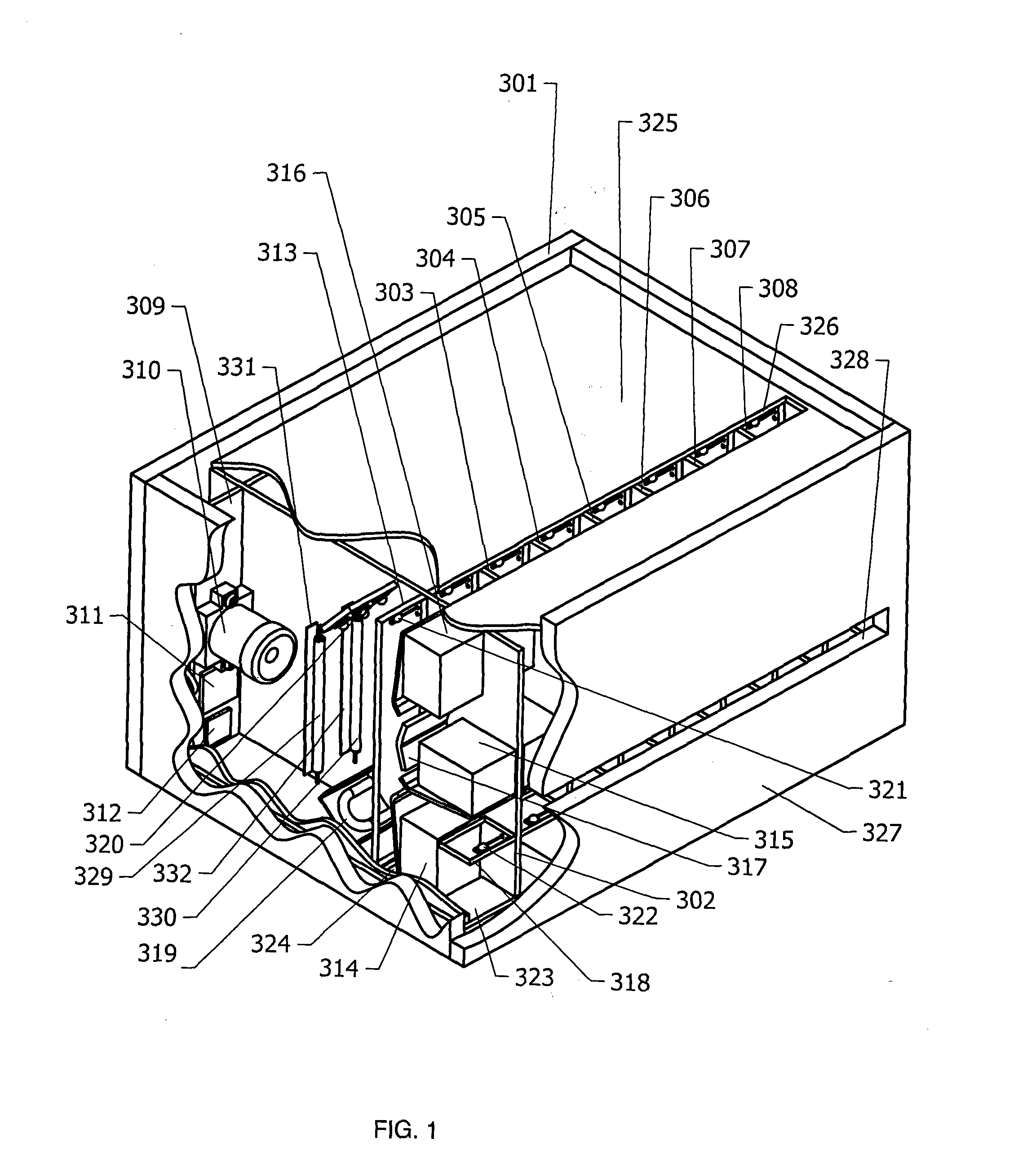
[0081]The device (FIG. 1) has the body 301, which contains eight identical sections, separated by dividing sheets 302, 303, 304, 305, 306, 307 and 308. We continue by describing the foremost section, shown in the figure through the cut partition. The section comprises the camera 310, which is placed on the printed circuit board 309, the image processor 311 with its memory 312, the glass window 313, electromagnet gates 314, 315 and 316, barrier 317 and transparent barrier 318, gas discharge lamp 319 and LED lamps 320 as well as attraction lights 321 and 322. The LED lamps 320 work in the red spectra, which is invisible to bees. The barrier 317 is v-shaped, creating a step, over which bees must climb and bend their bodies in such a way as to allow for better visibility of the gap between their thorax and abdomen and possible mite in the gap. The electromagnet gates 314, 315 and 316, and the light sources 319 and 320 are connected to the processor 311,...
example 2
The Second Embodiment of the Device
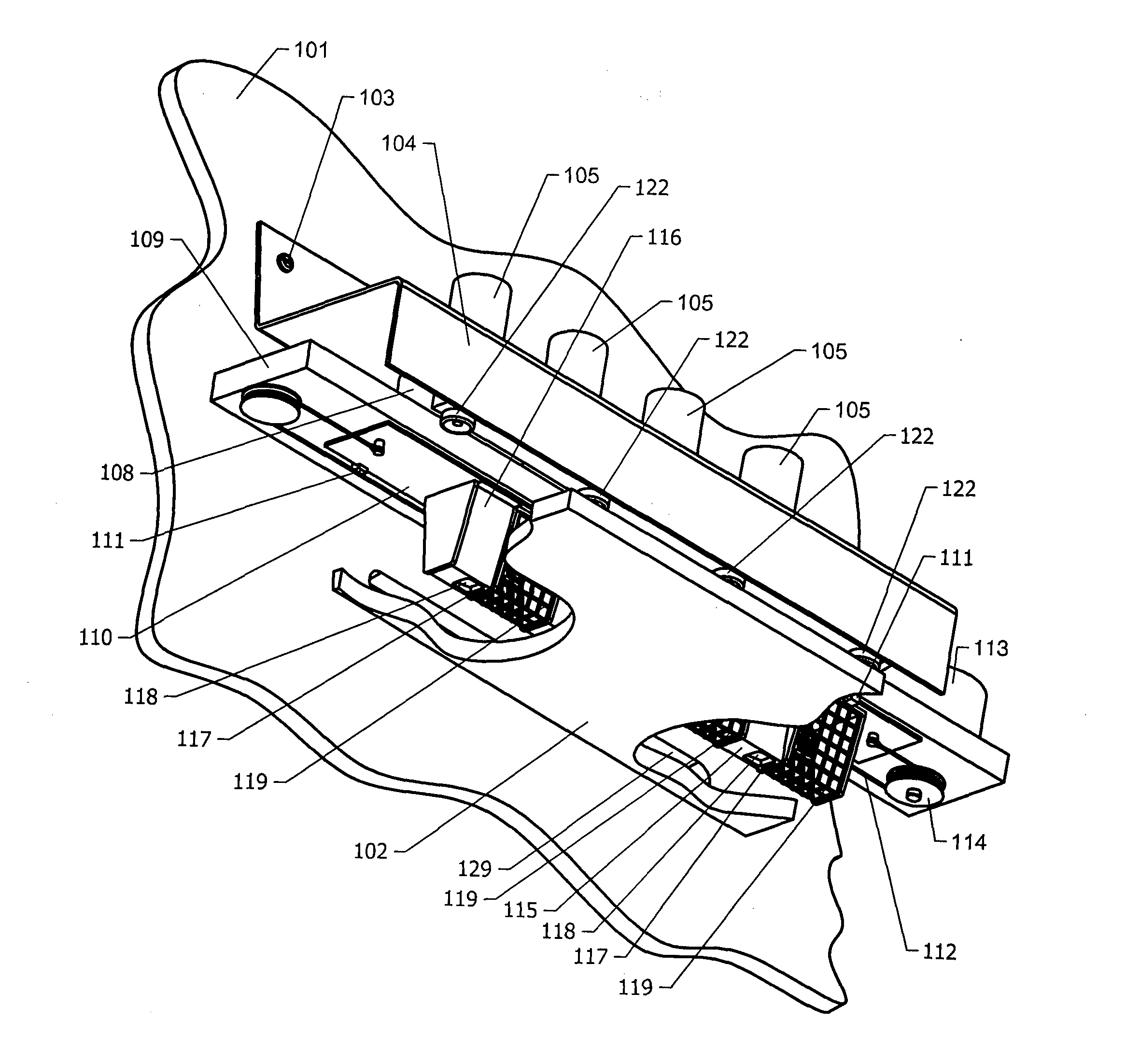
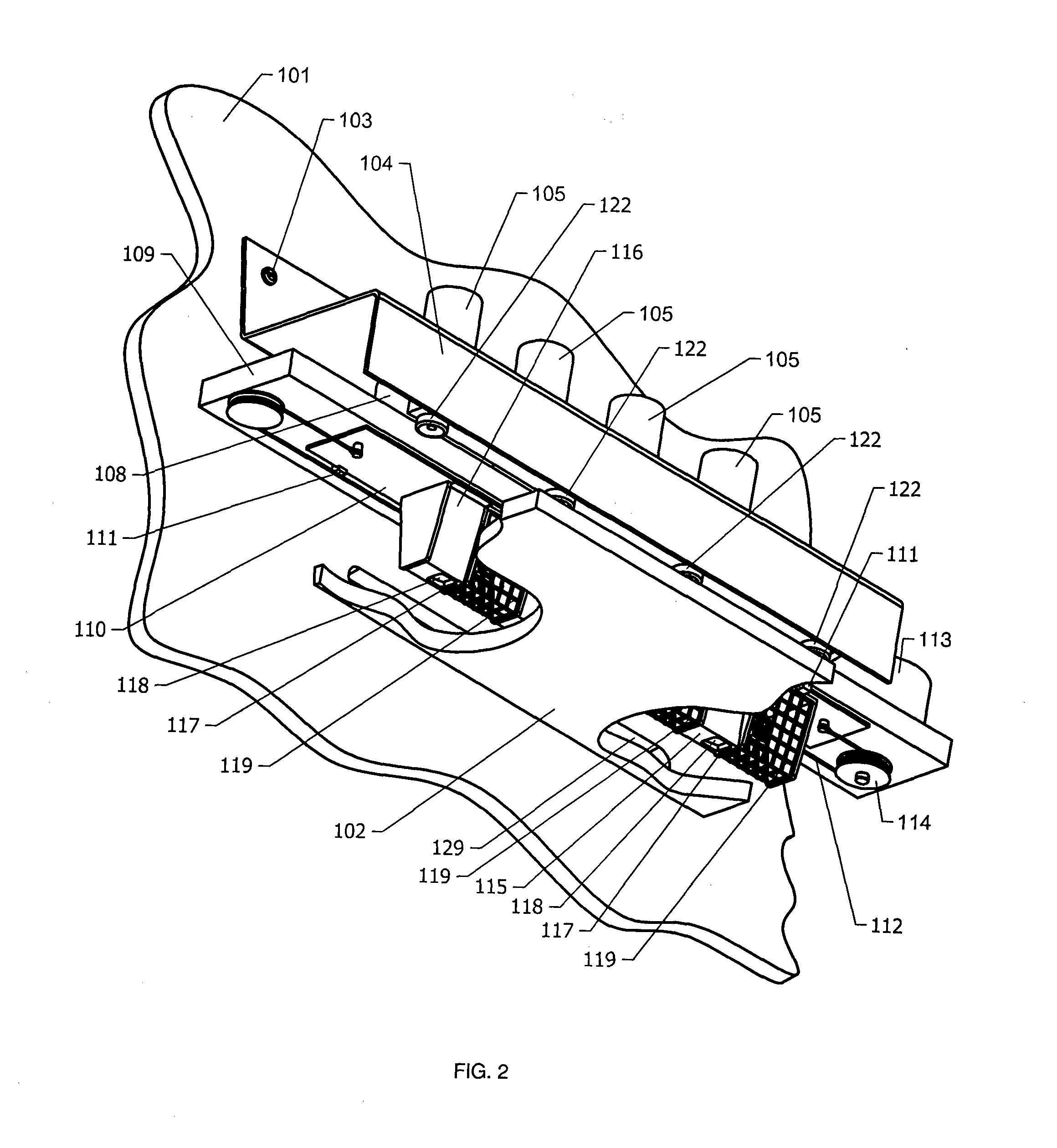
[0103]The device (FIG. 2, FIG. 3) is attached to the front wall 101 of the hive above the landing board 102, with screws 103. The device consists of a main body 104 that is overhanging as a cantilever above the landing board 102, and has four solenoids 105 been fastened. To the core of the solenoids 105, disk-shaped pistons 107 are fastened, which are arranged in cylinders 108. In no-current state of the solenoids 105, the pistons 107 are, under the pressure of the springs 106, in the lower position and the cores are pulled to their ultimate position out of the solenoids 105. The lower ends of the cylinders 108 are connected to a connecting plate 109, which has central air channels 124 and side air channels 125. On the lower side of the connecting plate 109, there is a sliding plate 110, which is directed by guides 111. Onto the shaft of a stepper motor 113, a driving wheel 114 is placed, which is connected to the sliding plate 110 via a cable 112....
example 3
The Third Embodiment of the Device
[0105]The device's third embodiment comprises all the components from second embodiment, however the landing board is made from a transparent material and below it is located an extra, underside camera assembly, similar to previously described camera assembly, except that it is directed upwards from underneath of the landing board, giving a view of the bees' undersides. The camera assembly, placed as described in the second embodiment, shall be referred to, here, as the upside camera assembly. The device of the third embodiment works similarly to the device of the second embodiment, except that the image processor of the upside camera assembly has an additional connection to the image processor of the underside camera assembly. The image processor of the underside camera assembly observes and analyses images of bees, moving on the landing board, similarly to the image processor of the second embodiment and forwards the coordinates of infected bees t...
PUM
 Abstract
Description
Claims
Application Information
 - R&D
- Intellectual Property
- Life Sciences
- Materials
- Tech Scout
- Unparalleled Data Quality
- Higher Quality Content
- 60% Fewer Hallucinations
Browse by: Latest US Patents, China's latest patents, Technical Efficacy Thesaurus, Application Domain, Technology Topic, Popular Technical Reports.
© 2025 PatSnap. All rights reserved.Legal|Privacy policy|Modern Slavery Act Transparency Statement|Sitemap|About US| Contact US: help@patsnap.com


