System and method for performing auto-location of a tire pressure monitoring sensor arranged with a vehicle wheel using confidence interval analysis and change of wheel direction

Active Publication Date: 2015-02-26
SCHRADER ELECTRONICS LTD
View PDF3 Cites 24 Cited by
  • Summary
  • Abstract
  • Description
  • Claims
  • Application Information

AI Technical Summary

Benefits of technology

[0011]In determining the COIN width value, change of wheel direction may need to be taken into consideration. The change of wheel direction may result in a shift in the perceived mean of correlated ABS tooth counts. Accordingly, the ch

Problems solved by technology

The extreme data points may be caused by nuisance factors such as road noise, vehicle vibrations, error in ABS source data, communication delays, etc.
Accordingly, the extreme data points may cause irregular and unexpected changes to the ABS data which may bias the auto-

Method used


Image

  • System and method for performing auto-location of a tire pressure monitoring sensor arranged with a vehicle wheel using confidence interval analysis and change of wheel direction
  • System and method for performing auto-location of a tire pressure monitoring sensor arranged with a vehicle wheel using confidence interval analysis and change of wheel direction
  • System and method for performing auto-location of a tire pressure monitoring sensor arranged with a vehicle wheel using confidence interval analysis and change of wheel direction

Examples


first embodiment

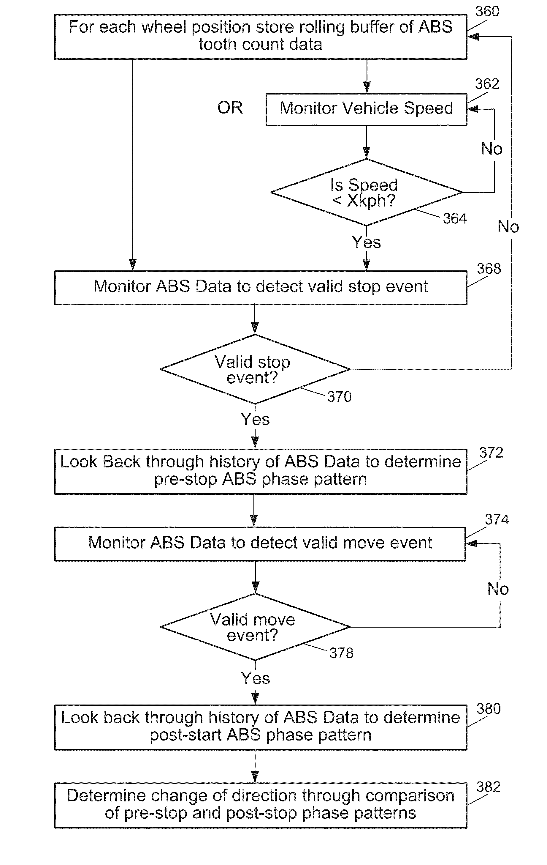
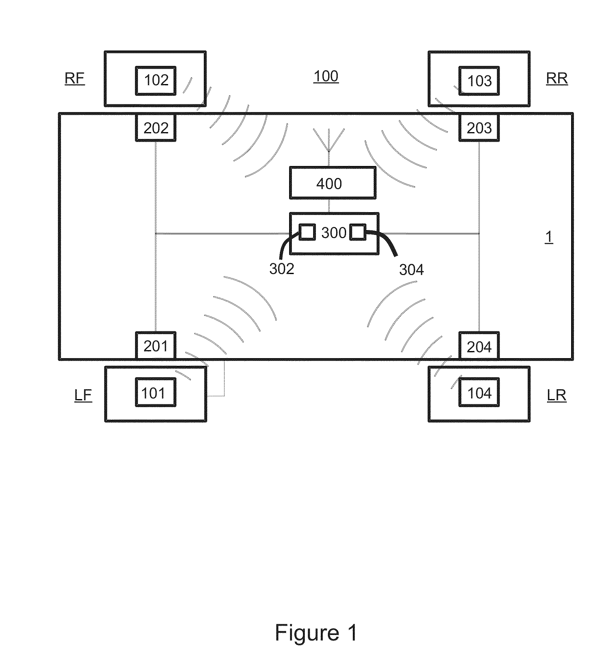
[0061]Referring to FIGS. 1-13, embodiments of obtaining ABS data for each RF transmission from a wheel unit are explained. FIG. 1 illustrates a tire pressure monitoring system 100 according to the present invention. The system 100 is arranged in a standard vehicle 1 having four wheels. Four wheels include a left front wheel (LF), a right front wheel (RF), a left rear wheel (LR) and a right rear wheel (RR). In another embodiment, the system 100 may be arranged in any other vehicle having a different number of wheels. The system 100 includes wheel units 101, 102, 103 and 104 that are associated with each wheel of the vehicle 1.

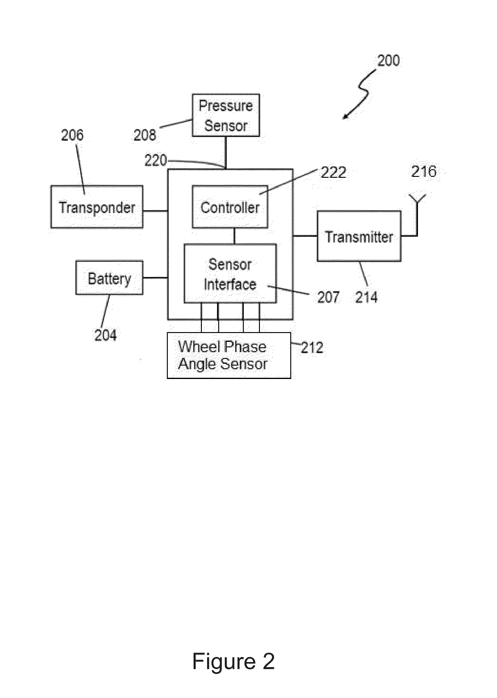
[0062]The system 100 further includes four antilock brake system (ABS) sensors 201, 202, 203 and 204. In this embodiment, ABS sensors 201, 202, 203, 204 are also associated with each wheel of the vehicle 1. Accordingly, each wheel is assigned with one of the wheel units 101, 102, 103 and 104 and one of ABS sensors 201, 202, 203 and 204. In another embodiment, AB...

second embodiment

[0106]Referring to FIG. 11C, the phase correlation data storage event trigger is described. FIG. 11C illustrates an RF message that includes temperature data 1130. In this embodiment, the temperature data 1130 includes 8 bits. As shown in FIG. 11C, 8 bits of temperature data indicate the normal operating temperature range of the tire pressure sensor 208 (FIG. 2). The normal operating temperature generally ranges from −40° C. to +125° C., and the temperature byte 1130 has the capability to indicate temperatures from −50° C. to +205° C. The temperatures above +125° C. may not have any practical application. Accordingly, some of the temperature bits are used to encode the wheel phase angle indication. By using the example illustrated in FIG. 11C, the temperature of +142° C. corresponds to 11000000 and the two most significant bits of the temperature byte are ‘H.’ The temperature of +142° C. is well above the maximum operating temperature. The code, 11000000 may be used to trigger a pha...


PUM


Abstract

A method for determining change of direction of a vehicle includes steps of maintaining a rolling window of ABS data indicative of ABS tooth count and capturing a relevant rolling window of ABS data at the predetermined one-measurement point; storing the rolling window of the ABS data indicative of ABS tooth in a buffer; monitoring the ABS data and detecting a valid stop event which causes the rate of change of ABS tooth count to substantially decrement to zero; and monitoring the ABS data and detecting a valid move event which causes the rate of change of ABS tooth count to substantially increment from zero. The method also includes steps of determining a pre-stop phase relationship between at least two wheels based on the ABS tooth count stored in the buffer immediately prior to the valid stop event; determining a post-start phase relationship between at least two wheels based on the ABS tooth count stored in the buffer immediately subsequent to the valid move event; and correlating the pre-stop phase relationship and the post-start phase relationship to determine change of direction and confidence level.

Description

PRIORITY[0001]This application is a continuation-in-part of U.S. application Ser. No. 13 / 973,855 filed Aug. 22, 2013, entitled “System and method for performing auto-location of a tire pressure monitoring sensor arranged with a vehicle wheel using confidence interval analysis and rollback events,” disclosure of which is incorporated here in its entirety.BACKGROUND[0002]1. Technical Field[0003]This application relates generally to a system and method for performing auto-location of a wheel in a vehicle and more particularly to a tire pressure monitoring system and method for performing auto-location of a tire pressure monitoring sensor arranged with a vehicle wheel using confidence interval analysis. This application further relates to a tire pressure monitoring system and method for performing auto-location of a tire pressure monitoring sensor using confidence interval analysis which takes into consideration change of wheel direction.[0004]2. Related Art[0005]In tire pressure monito...

Claims


Application Information

Patent Timeline
IPC IPC(8): B60C23/04B60C23/00
CPCB60C23/00B60C23/0488B60T8/171B60T8/172B60W40/10G01P13/045B60C23/0416B60C23/0489B60W40/105B60C23/04G01P13/04
Inventor FRIEL, EDWARDGRAHAM, GARYWALKER, PETERMILLEN, ALAN
Owner SCHRADER ELECTRONICS LTD
Why Eureka
Try Eureka