Housing part for a housing with flameproof encapsulation comprising a porous body

a porous body and housing technology, applied in fireproofing, electrical apparatus casings/cabinets/drawers, container discharging methods, etc., can solve the problems of not allowing flames and sparks or the like to escape from the interior of the container, unable to compensate for small pressure differences continuously, and certain overpressure to appear initially in the housing. , to achieve the effect of avoiding water penetration and high gas volume flow

Active Publication Date: 2015-03-05
R STAHL SCHALTGERATE
View PDF4 Cites 27 Cited by
  • Summary
  • Abstract
  • Description
  • Claims
  • Application Information

AI Technical Summary

Benefits of technology

[0008]It is an object of the present invention to provide a housing part for an explosion-protected housing with flameproof encapsulation which ensures a high gas volume flow and which nonetheless avoids the penetration of water into the housing in a simple manner.
[0011]Accordingly, a water-repellent membrane at the passage can be foregone. The gas volume flow through the porous body is thus possible in an unhindered manner. The hydrophobic surface does not noticeably impact the gas volume flow. A pressure compensation can thus also take place in an unhindered manner in the case of smaller pressure differences. In addition, the design and assembly of the housing part is simplified. In the event of an explosion in the interior of the housing, the housing part can also limit the housing pressure as a pressure release device. Due to the pressure release, the housing itself can be constructed to be less stable than without such a pressure release. In the case of a sudden pressure rise during an explosion, an unhindered large gas volume flow through the porous body is ensured.
[0013]The hydrophobic surface can contain a fluorocarbon and / or a silane. A fluorocarbon and / or silane has the advantage that in addition to its hydrophobic effect, it also protects against the penetration of oily liquids into the interior of the housing. In addition, the adhesion of dirt particles to the porous body is reduced, so that an impacting of the gas volume flow by a clogging of pores can be avoided or can at least reduced. For example, polytetrafluoroethylene can be used as material for the hydrophobic surface. In addition or in the alternative, the hydrophobic surface can also contain fats and / or waxes. The porosity and / or the pore size of the pores of the porous body can be smaller in the area of the hydrophobic surface than outside of the area comprising the hydrophobic surface.
[0014]In the case of a preferred exemplary embodiment, the porous body is formed by means of a randomly oriented fiber structure part. The porous body comprises fibers, which are intertwined and which are arranged in an unordered manner, which form the randomly oriented fiber structure part. Preferably, the fibers have a diameter of at least 70 micrometers and of maximally 130 micrometers. Preferably, all of the fibers or at least a part of the fibers of the porous body can be provided with the hydrophobic surface. It is possible to thereby provide the fibers with the hydrophobic surface prior to the intertwining and thus prior to forming the randomly oriented fiber structure part. As an alternative, the fibers or at least a part of the fibers can be provided with the hydrophobic surface after the formation of the randomly oriented fiber structure part.
[0020]To prevent the penetration of splash water, which hits the porous body at a high speed, into the interior of the housing, a splash water protection, preferably a splash water protective cover, can be present in the area of the outer side of the porous body in the housing part. The porous body can thus be protected from splash water which is directed to the housing part at a high pressure.

Problems solved by technology

The porous body thereby represents a gas-permeable barrier, which does not allow for flames and sparks or the like to escape out of the interior of the container to the outside.
It is disadvantageous thereby that a certain overpressure must initially appear within the housing before the flap opens at all.
Smaller pressure differences cannot be compensated continuously.
However, the membrane limits the volume or mass flow, respectively, through the porous body.
However, the design described therein is not suitable for explosion-proof applications.
However, an explosion protection is also not ensured.

Method used


Image

  • Housing part for a housing with flameproof encapsulation comprising a porous body
  • Housing part for a housing with flameproof encapsulation comprising a porous body
  • Housing part for a housing with flameproof encapsulation comprising a porous body

Examples


Embodiment Construction

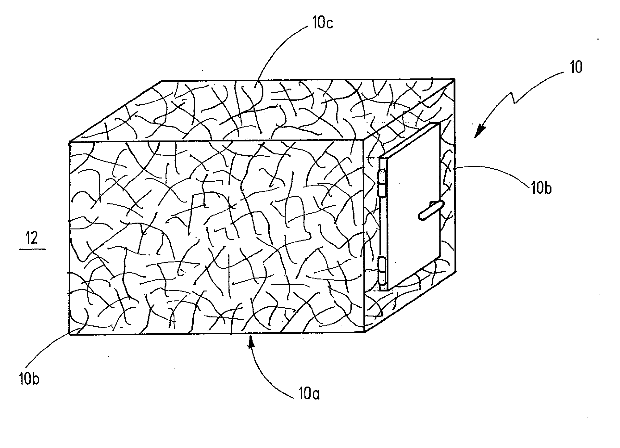
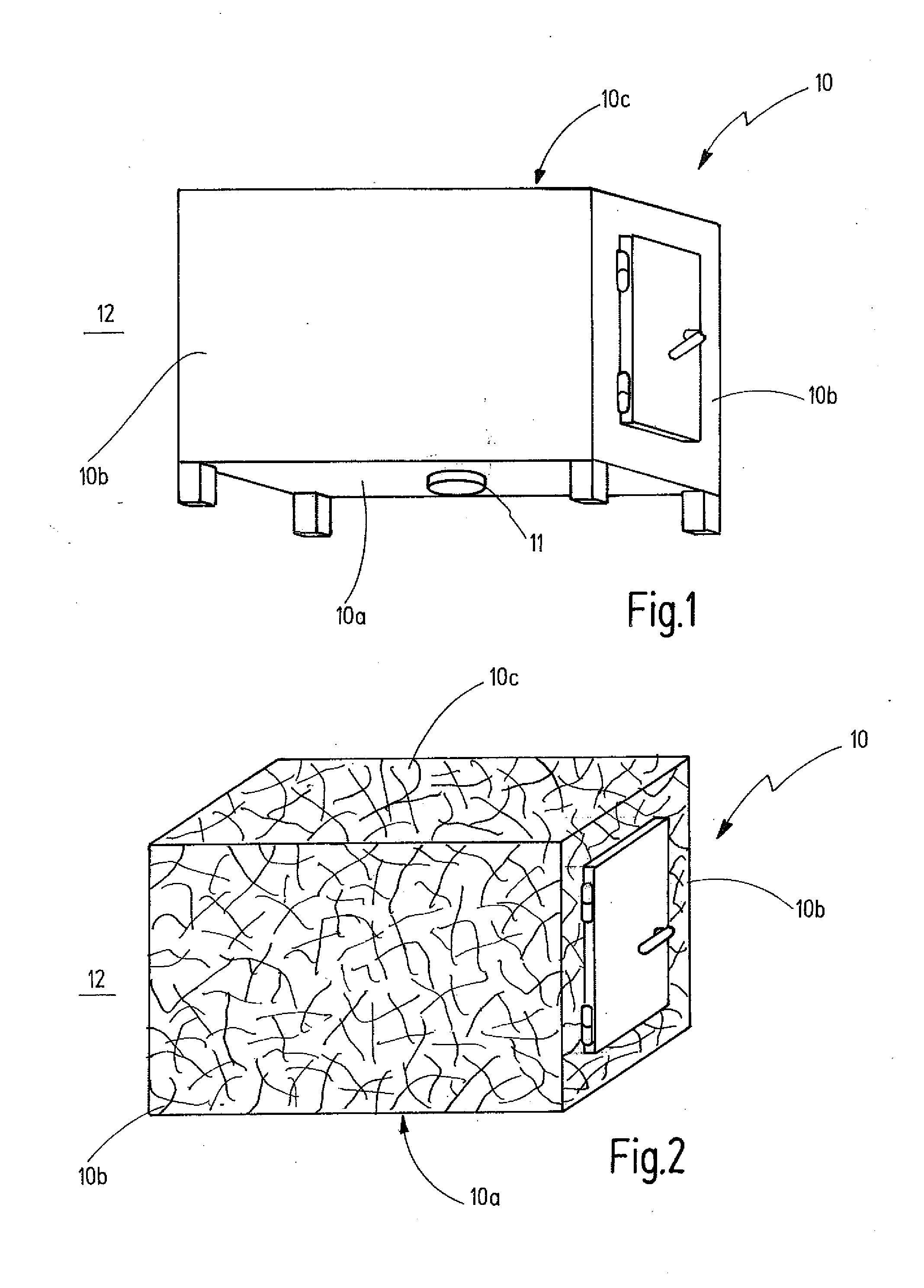
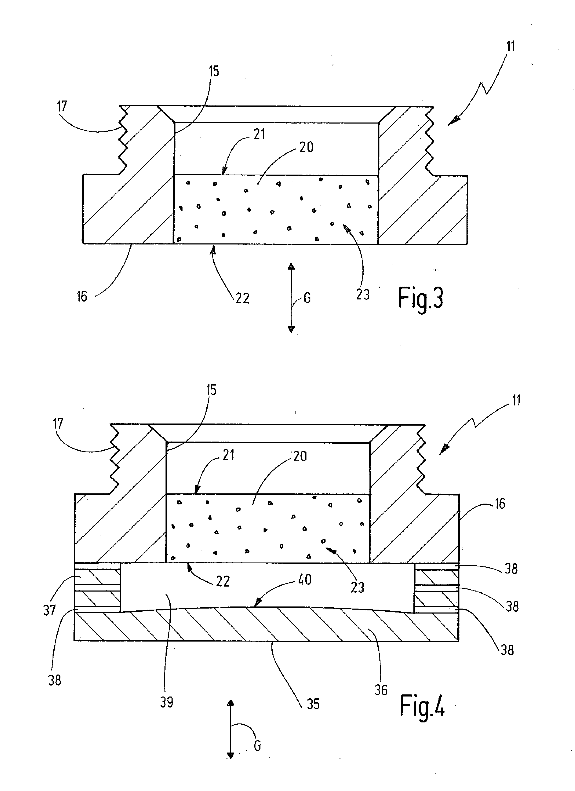
[0030]Referring now more particularly to FIG. 1 of the drawings, there is shown an illustrative explosion-protect housing with flameproof encapsulation 10 in accordance with the invention. The explosion-protect housing with flameproof encapsulation 10 in particular provides an ignition protection type “pressure-resistant encapsulation” (Ex-d). It comprises a flow-through device 11 in a housing bottom 10a, a housing wall 10b, or a housing top 10c of the housing 10. Exemplary embodiments for the flow-through device 11 are illustrated in FIGS. 3 and 4.

[0031]The flow-through device 11 serves as pressure release device and / or as pressure compensating device. In its function as pressure compensating device, pressure differences between the interior of the housing 10 and the surrounding area 12 outside of the housing 10 are compensated, in that a gas volume can flow through the flow-through device 11 from the interior into the surrounding area 12 or vice versa. Such pressure differences ca...


PUM

PropertyMeasurementUnit
diameteraaaaaaaaaa
diameteraaaaaaaaaa
pore sizeaaaaaaaaaa

Abstract

A housing part for an explosion-protected housing (10) with flameproof encapsulation. The housing part comprises a porous body (20) in a passage (15) of the housing part. The passage (15) is closed in a flameproof manner by means of the porous body (20). The porous body (20) comprises an inner side (21) assigned to the interior of the housing (10) and an outer side (22) assigned to the surrounding area (12) comprising the explosive atmosphere. A gas volume flow can pass through the porous body (20), entering the porous body (20) on the inner side (21) and escape on the outer side (22) or vice versa. To prevent the penetration of water or of other aqueous liquids into the interior of the housing (10), the porous body (20) comprises a hydrophobic surface (B) in at least one area (31).

Description

FIELD OF THE INVENTION[0001]The invention relates to a housing part for an explosion-protected housing of the flameproof encapsulation type. For example, a housing wall, a housing wall section or a nozzle, which can be connected to a housing wall, can serve as housing part. The explosion-protected housing preferably is embodied in an ignition protection type “flameproof encapsulation” (Ex-d). Typically, electrical and / or electronic component parts or components which can represent ignition sources for an explosive atmosphere present in the surrounding area outside of the housing are located in the explosion-protected housing. The explosion-protected housing with flameproof encapsulation separates such ignition sources from the explosive atmosphere.BACKGROUND OF THE INVENTION[0002]The housing or the housing part typically comprises a porous body which serves as a flow-through device for providing a gas exchange connection between the interior of the housing and the surrounding area. ...

Claims


Application Information

Patent Timeline
Patent Type & Authority Applications(United States)
IPC IPC(8): B65D81/02
CPCB65D81/022A62C2/00A62C3/00E04B1/94A62C4/00H02B1/28A62C3/002H05K5/0216H05K5/0209H05K5/0213
Inventor LIMBACHER, BERNDMANN, ULRICH
Owner R STAHL SCHALTGERATE
Why Eureka
Try Eureka