Aircraft window, closing member for opening portion, and aircraft

Active Publication Date: 2015-03-05
MITSUBISHI AIRCRAFT
View PDF17 Cites 6 Cited by
  • Summary
  • Abstract
  • Description
  • Claims
  • Application Information

AI Technical Summary

Benefits of technology

[0006]Meanwhile, inside an aircraft, radio waves or electromagnetic waves (hereinafter, both as “electromagnetic waves”) from various electronics such as mobile telephones, game machines, and notebook computers, and PEDs (Personal Electro Devices) such as active-type RFID (Radio Frequency Identification) tags attached to air cargos may have adverse effects on, for example, communications with airport control towers, and communications or controls of navigation for a flight along a predetermined route. Thus, as is well known, passengers are asked to refrain from using various electronics inside the aircraft.
[0007]Electromagnetic waves invade an airframe of the aircraft, e.g., a cabin (a seat space), a cockpit (a flight deck), and an avionics bay through a window provided in an opening portion formed in the airframe.
[0008]To prevent the invasion of the electromagnetic waves, an electromagnetic shield film is held between a plurality of window panels constituting the window (e.g., see JP 2003-523911A (Translation of PCT Application)).
[0009]As shown in FIG. 1

Problems solved by technology

1) a greater dependence on electric/electronic systems that execute functions required for continued safe flight and landing of the aircraft;
2) a decrease in electromagnetic shielding by certain types of composite materials (fiber reinforced resins) used for designing the aircraft;
3) an increase in the susceptibility (sensitivity) of the electric/electronic systems to HIRF along with the increase in operating rates of data buses or processors, the higher densities of ICs (Integrated Circuits) and cards, and the higher sensitivity of electronics;
4) an expansion of a usage frequency particularly to a high-frequency band of 1 GHz or higher;
5) an increase in the severity of HIRF environments along with increases in the number of RF transmitters and electric power; and
6) an adverse effect on some aircrafts during exposure to HIRF.
Meanwhile, inside an aircraft,

Method used


Image

  • Aircraft window, closing member for opening portion, and aircraft
  • Aircraft window, closing member for opening portion, and aircraft
  • Aircraft window, closing member for opening portion, and aircraft

Examples


Example

First Embodiment

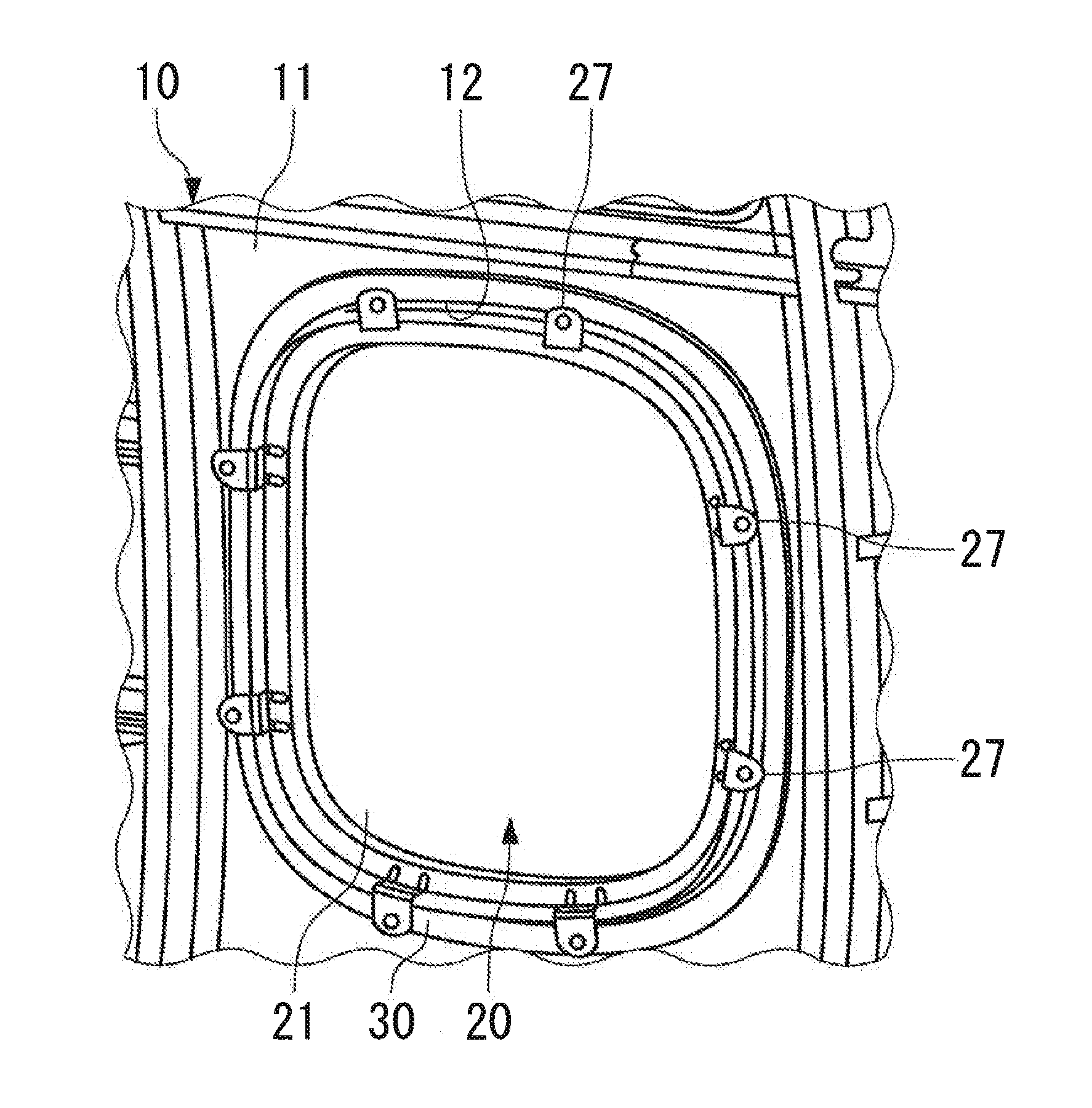
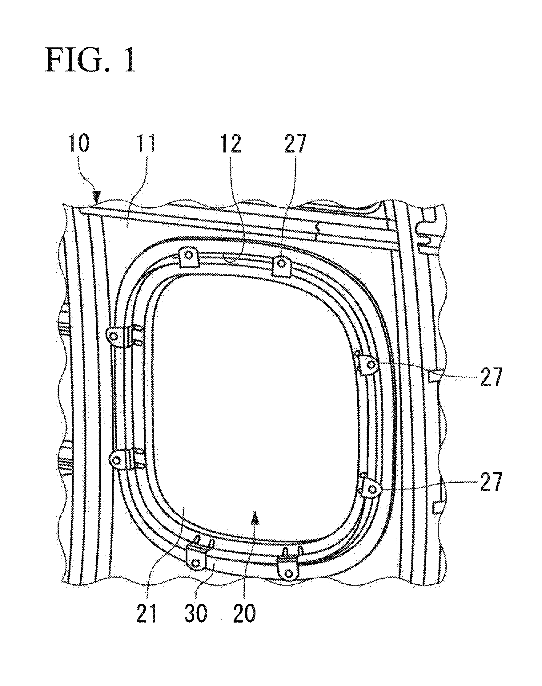
[0054]FIG. 1 shows a window 20 that is provided in a cabin of an aircraft.

[0055]The window 20 is provided in an opening portion 12 that is formed in a skin 11 constituting an airframe 10 of the aircraft. The window 20 includes a window body 21 having light transmissibility, and a window frame 30 that surrounds the window body 21. The window body 21 is fixed to the skin 11 via the window frame 30 by a fixing members 27 arranged at a plurality of positions along the peripheral edge of the opening portion 12.

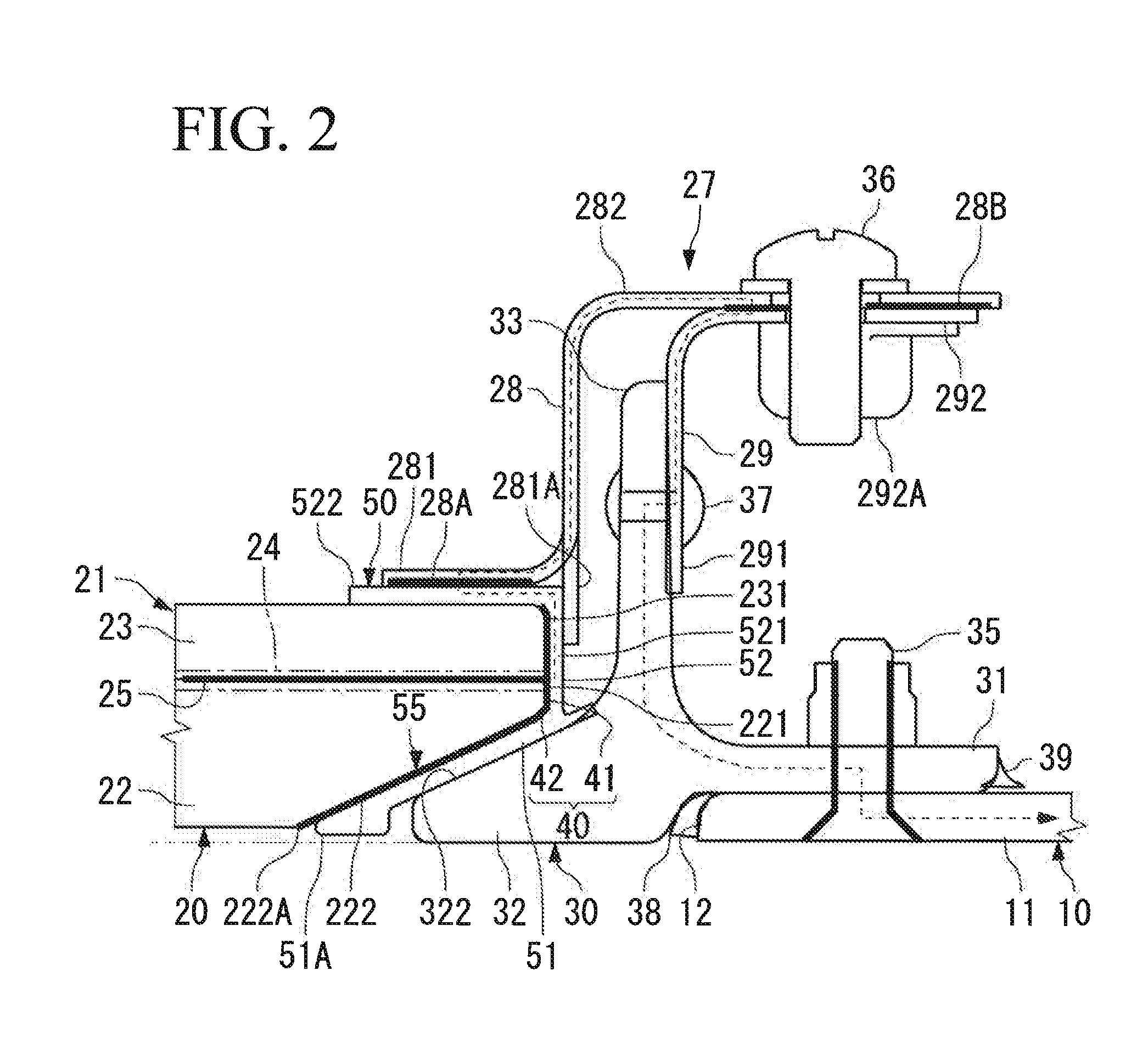
[0056]As shown in FIG. 2, the window body 21 includes two window panels 22 and 23, and an electromagnetic shield mesh (an electromagnetic shield layer) 25 that is interposed between the window panels 22 and 23. The electromagnetic shield layer 25 is formed into a plane size substantially equal to that of the window panels 22 and 23.

[0057]The window body 21 is a laminate including the window panels 22 and 23 and the electromagnetic shield layer 25.

[0058]The window pa...

Example

Second Embodiment

[0145]Next, an aircraft window according to a second embodiment of the present invention is described with reference to FIG. 8.

[0146]In the second embodiment, differences from the first embodiment are mainly described. The same components as those of the first embodiment are assigned the same reference numerals.

[0147]The window of the second embodiment includes a first conductive layer 61 that is formed on the side surface (the end surface) of the window body 21, and a non-conductive gasket 70.

[0148]The first conductive layer 61 is formed on the side surface 221 of the window panel 22, and is brought into conduction with the outer periphery of the electromagnetic shield layer 25. The first conductive layer 61 does not extend to the inclined side surface 222 of the window panel 22 facing the holding section 32 of the window frame 30. An end portion on the airframe outer side of the first conductive layer 61 is located at a corner portion C formed by the side surface ...


PUM


Abstract

An aircraft window includes: a window body including window panels, and an electromagnetic shield layer laminated on the window panels; a window frame that is made of a conductive material, and that surrounds the window body; a rubber-based gasket provided with conductivity, the gasket being at least partially held between the window body and the window frame; and a conductive layer that is located between the window body and the gasket, and that brings the electromagnetic shield layer and the gasket into conduction with each other. The window frame includes a holding section that holds the window body via the gasket from an airframe outer side. The conductive layer extends to a portion of the window body facing the holding section.

Description

BACKGROUND OF THE INVENTION[0001]1. Field of the Invention[0002]The present invention relates to an aircraft window having an electromagnetic shielding function, and a closing member for an opening portion having an electromagnetic shielding function.[0003]2. Description of the Related Art[0004]During a cruising flight, a landing or a takeoff, an aircraft is required to be able to fly safely without occurrence of malfunctions or unforeseen behaviors (up-set) to the aircraft in high intensity radiated fields (HIRF), which represent electromagnetic environments from radios, televisions, radars, transmitters, and other sources. For this reason, it is necessary to take HIRF protection measures as required in (14CFR) Sections 23.1308, 25.1317, 27.1317, and 29.1317, High-intensity Radiated Fields (HIRF) protection, which stipulate Regulations (airworthiness requirements) of FAA (Federal Aviation Administration).[0005]Recently, the importance of the protection of electric / electronic system...

Claims


Application Information

Patent Timeline
IPC IPC(8): H05K9/00B64C1/14E06B5/18B64D45/00
CPCH05K9/0094B64D45/00E06B5/18B64C1/1492H05K9/0075B64C1/1484B64C1/1476B64D45/02E06B3/62E06B2003/6258H05K9/0005
Inventor YOKOI, TAKASHI
Owner MITSUBISHI AIRCRAFT
Why Eureka
Try Eureka