Location detection device

a technology of location detection and detection device, which is applied in the direction of instruments, computing, electric digital data processing, etc., can solve the problems of increased cost and reduced transparency, and achieve the effect of enhancing the blocking reducing the leakage of noise emitted from the surface of the display device to the outside, and reducing the noise emitted from the display devi

Inactive Publication Date: 2015-03-05
ALPINE ELECTRONICS INC
View PDF13 Cites 2 Cited by
  • Summary
  • Abstract
  • Description
  • Claims
  • Application Information

AI Technical Summary

Benefits of technology

[0010]The plurality of transparent electrodes preferably include a plurality of first electrodes arranged along a first direction and a plurality of second electrodes arranged along a second direction intersecting the first direction. The location detection unit preferably inputs a location detection signal to part of the first electrodes and also captures a signal corresponding to the location detection signal output from part of the second electrodes. The low impedance setting unit preferably puts transparent electrodes other than transparent electrodes used for input of the location detection signal and output of the signal corresponding to the location detection signal into a low impedance state. Thus, since most electrodes other than a first electrode and a second electrode that are used for location detection are in a low impedance state, the effect of blocking noise emitted from the surface of the display device may be enhanced.
[0011]The low impedance setting unit preferably puts the transparent electrodes into a low impedance state by connecting the transparent electrodes to a fixed potential. In particular, the fixed potential is preferably a ground potential, and the low impedance setting unit preferably puts the transparent electrodes into a low impedance state by grounding the transparent electrodes. Thus, a shield layer is implemented by using the transparent electrodes, and leakage of noise emitted from the surface of the display device to the outside may be reduced.
[0012]Preferably, switches are individually connected to each of the plurality of transparent electrodes, and switching between input of the location detection signal or output of the signal corresponding to the location detection signal and connection to the fixed potential is performed via the switches. Thus, simple addition of switches enables certain transparent electrodes to be put into a low impedance state at a certain point in time.
[0013]Preferably, other transparent electrodes adjacent to parts of the transparent electrodes in which input of the location detection signal or output of the signal corresponding to the location detection signal is performed are not connected to the fixed potential, but are opened. This enables a reduction in noise emitted from the display device while maintaining the sensitivity of location detection.
[0014]The location detection device according to one aspect of the present disclosure is mounted in a vehicle together with an AM radio, Alternatively, the location detection device according to another aspect of the present disclosure is mounted in the same housing in which the AM radio is mounted. Thus, regarding the AM radio mounted in the vehicle, the effect of noise emitted from the display device may be reduced.
[0015]While a broadcast wave is being received by the AM radio, the transparent electrodes are preferably set into a low impedance state by the low impedance setting unit. Alternatively, when a reception frequency of a broadcast wave being received by the AM radio coincides with a frequency of noise emitted from the display device, the transparent electrodes are preferably set into a low impedance state by the low impedance setting unit. When a reception frequency of a broadcast wave being received by the AM radio coincides with a frequency of a harmonic component of a horizontal synchronous frequency of the display device, the transparent electrodes are preferably set into a low impedance state by the low impedance setting unit. This may prevent noise emitted from the display device from being mixed into an AM broadcast being received.

Problems solved by technology

In the above display device equipped with the touch panel disclosed in Japanese Unexamined Patent Application Publication No. 2012-68760, a shield layer composed of the transparent conductive film is superposed on a surface of the display device, such that there is a problem in that transparency is reduced.
Furthermore, since the shield layer has to be added in addition to the display device and the touch panel, there is a problem in that a manufacturing process or an assembly process becomes complicated and results in an increase in costs.

Method used


Image

  • Location detection device
  • Location detection device
  • Location detection device

Examples


Embodiment Construction

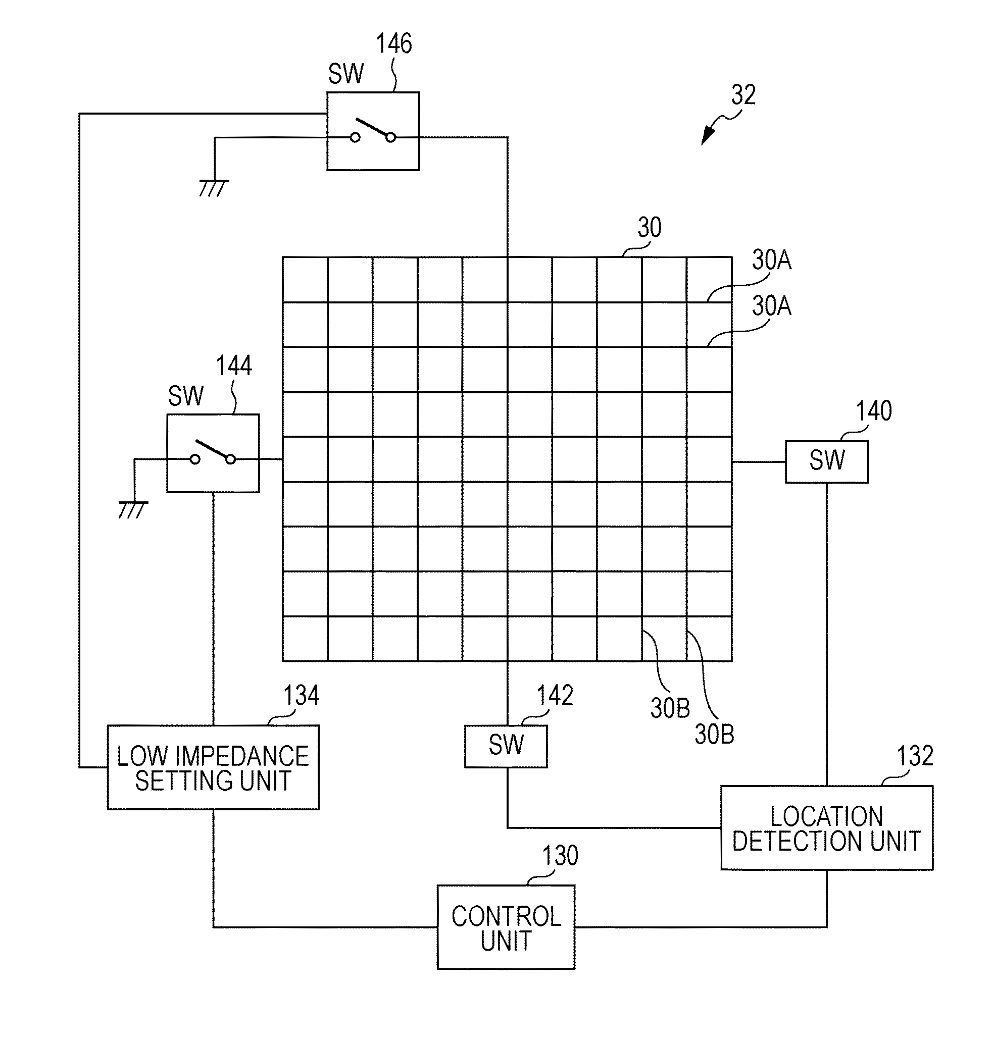
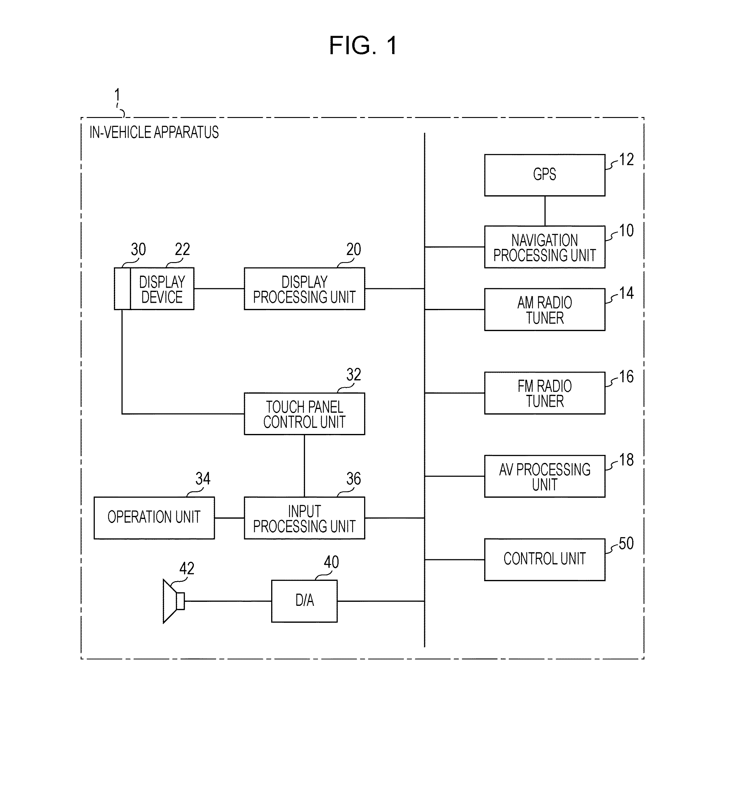
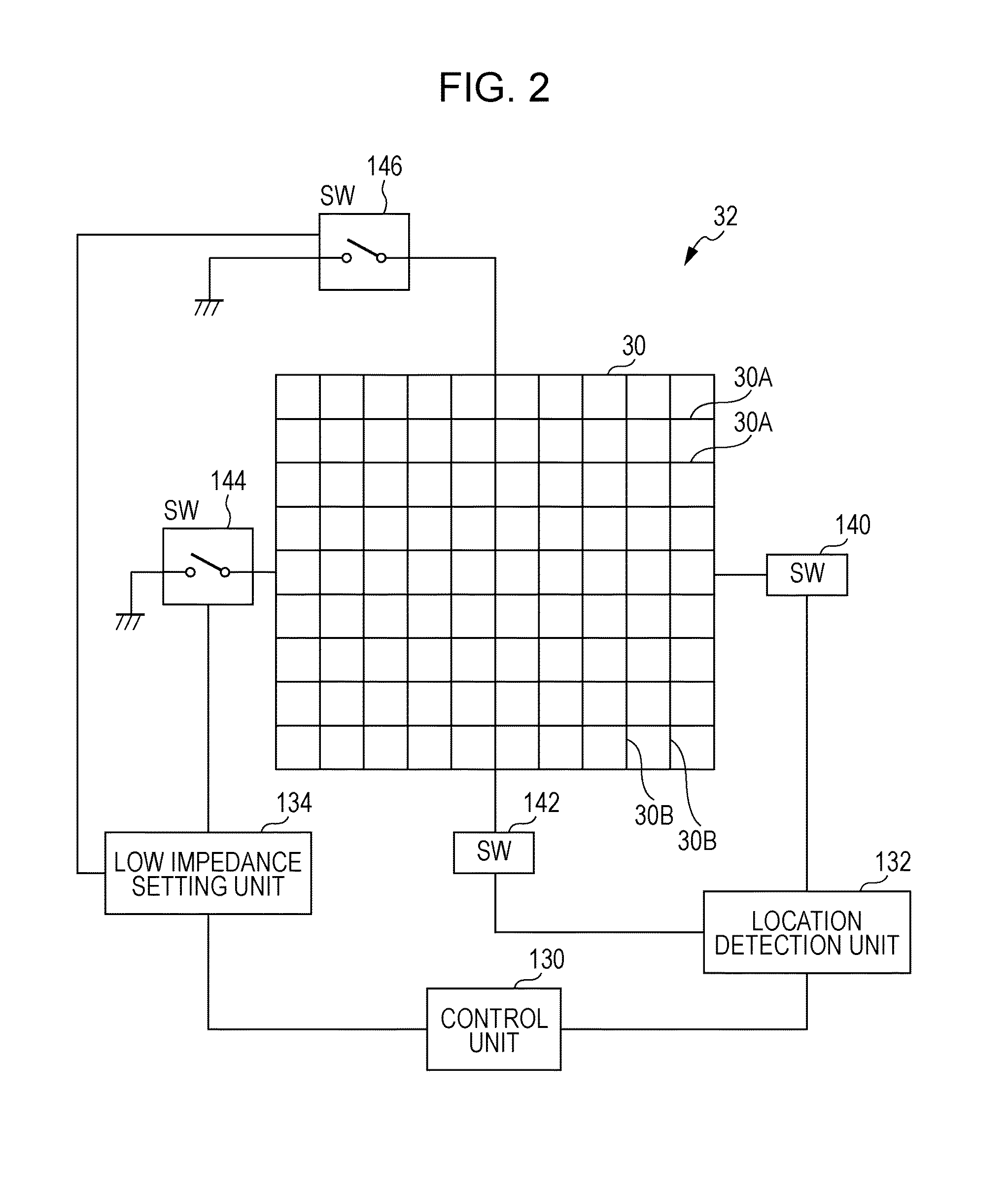
[0022]An in-vehicle apparatus according to an embodiment of the present disclosure in which a display device is equipped with a touch panel will be described below with reference to the drawings. FIG. 1 illustrates the configuration of the in-vehicle apparatus according to the embodiment. As illustrated in FIG. 1, an in-vehicle apparatus 1 includes a navigation processing unit 10, an amplitude modulation (AM) radio tuner 14, a frequency modulation (FM) radio tuner 16, an audio-visual (AV) processing unit 18, a display processing unit 20, a display device 22, a touch panel 30, a touch panel control unit 32, an operation unit 34, an input processing unit 36, a digital-to-analog converter (D / A) 40, a speaker 42, and a control unit 50.

[0023]The navigation processing unit 10 is used together with a global positioning system (GPS) device 12 that detects the location of the vehicle in which the in-vehicle apparatus 1 is mounted. and performs, by using map data, a navigation operation to gu...


PUM

PropertyMeasurementUnit
horizontal synchronous frequencyaaaaaaaaaa
sizeaaaaaaaaaa
frequencyaaaaaaaaaa

Abstract

In a location detection device, a capacitive touch panel is disposed on a surface of a display screen of a display device. The location detection device includes a touch panel that includes a plurality of transparent electrodes arranged in mutually intersecting directions; a location detection unit that detects a touch location of an instruction body by selecting parts of the plurality of transparent electrodes and measuring a change in capacitance between the parts; and, a low impedance setting unit that, at a point in time when the location detection unit selects the parts of the transparent electrodes, puts remaining transparent electrodes into a low impedance state.

Description

RELATED APPLICATION[0001]The present application claims priority to Japanese Application Number 2013-182677, filed Sep. 4, 2013, the entirety of which is hereby incorporated by reference.BACKGROUND[0002]1. Field[0003]The present disclosure relates to a location detection device including a capacitive touch panel superposed on a surface of a display device, such as a liquid crystal display (LCD).[0004]2. Description of the Related Art[0005]A display device equipped with a touch panel is known in the art. Such display device includes a touch panel provided on an observation side of a display panel. A shield layer provided between the display panel and the touch panel prevents electrical noise (see, for example, Japanese Unexamined Patent Application Publication No. 2012-68760). In this display device equipped with the touch panel, the shield layer is composed of a transparent conductive film containing a conductive polymer, so that optical properties of the display device are not degr...

Claims


Application Information

Patent Timeline
Patent Type & Authority Applications(United States)
IPC IPC(8): G06F3/044G02F1/1343
CPCG06F3/044G02F1/134336G02F1/13439G06F3/0416G06F3/0446G06F3/04166G06F3/04182G06F3/0443
Inventor KITAMURA, KAZUHIRO
Owner ALPINE ELECTRONICS INC
Why Eureka
Try Eureka