Lighting equipment for generating light of high luminance

a technology of lighting equipment and luminance, which is applied in the direction of lighting and heating equipment, instruments, display means, etc., can solve the problems of high thermal stress, limited adjustment of numeral aperture na of excitation light, and difficulty in implementing sufficient cooling and adequate removal of heat from led devices, etc., to achieve greatly simplified heat removal, high efficiency, and high luminance

Active Publication Date: 2015-03-05
SCHOTT AG
View PDF11 Cites 15 Cited by
  • Summary
  • Abstract
  • Description
  • Claims
  • Application Information

AI Technical Summary

Benefits of technology

[0012]What would be desirable, therefore, is lighting equipment for generating light of high luminance, especially white light, with sufficiently high efficiency and with greatly simplified heat removal.
[0013]In addition, the lighting equipment should permit simple and safe installation of the necessary elements, in particular a radiation source and a conversion medium.

Problems solved by technology

A drawback therein is the complexity of implementing sufficient cooling and adequate removal of heat from the LED device.
Comparatively high power dissipation in the conversion medium, which may lead to heating and high thermal stress in the conversion medium may prove to be disadvantageous because heat removal is difficult with such an arrangement of radiation device and conversion medium.
Both the geometry of the cooling and the limited possibility to adjust the numeral aperture NA of the excitation light through scattering are unfavorable circumstances in lighting equipment working in transmission.
Also in this case light would be lost by backscattering.
Direct irradiation of the conversion medium from the laser diode is disadvantageous because the numeral aperture NA of the emitted radiation is usually very high.
Therefore, if the spacing would be chosen very small, strong shadowing would result due to the necessary casing.
However, arbitrarily small focal lengths are not feasible.
Arbitrarily small focal lengths cannot be implemented, because the diameter of the circular cross section of the rod lens must be at least greater than the emission spot of the fiber.
However, with a GRIN lens, aberration errors are serious in the outer region of the lens unless a specifically optimized refractive index profile is used.
However, the refractive power of plano-convex rod lenses of a refractive index of n=1.5 is limited, so that a combination with high-aperture fibers is impossible.
In case of a conversion medium comprising a body that has edges, care should be taken to ensure that the excitation light is not incident upon an edge, since this may lead to an inhomogeneous heat distribution and a lower efficiency of remission.
A drawback that may result from the geometric arrangement of the excitation light source and the conversion medium is that the excitation light source may be placed within the range of the beam path, i.e. along the optical path, of the secondary radiation, because the excitation light is not transmitted, but remitted.
This may lead to unwanted shadowing effects, since the excitation light source and / or the carrier device is in the beam path of the secondary radiation.
However, an increase of the spacing may lead to a significant loss of luminance, since with increasing spacing the light spot is typically enlarged, and luminance decreases accordingly.
This may also cause an increase in the beam parameter product.
Conversion typically produces heat in the conversion medium, which unless appropriately removed may have an adverse effect on radiation conversion, for example may result in a reduction of conversion efficiency or even destruction of the conversion medium.
Such filtering may result in a lower efficiency of conversion.
This radiation may then be converted again so that most favorably the loss in efficiency caused by the filter can be limited.

Method used


Image

  • Lighting equipment for generating light of high luminance
  • Lighting equipment for generating light of high luminance
  • Lighting equipment for generating light of high luminance

Examples


Embodiment Construction

[0146]In the following detailed description of preferred embodiments, for the sake of clarity the same reference numerals designate substantially similar elements in or on these embodiments.

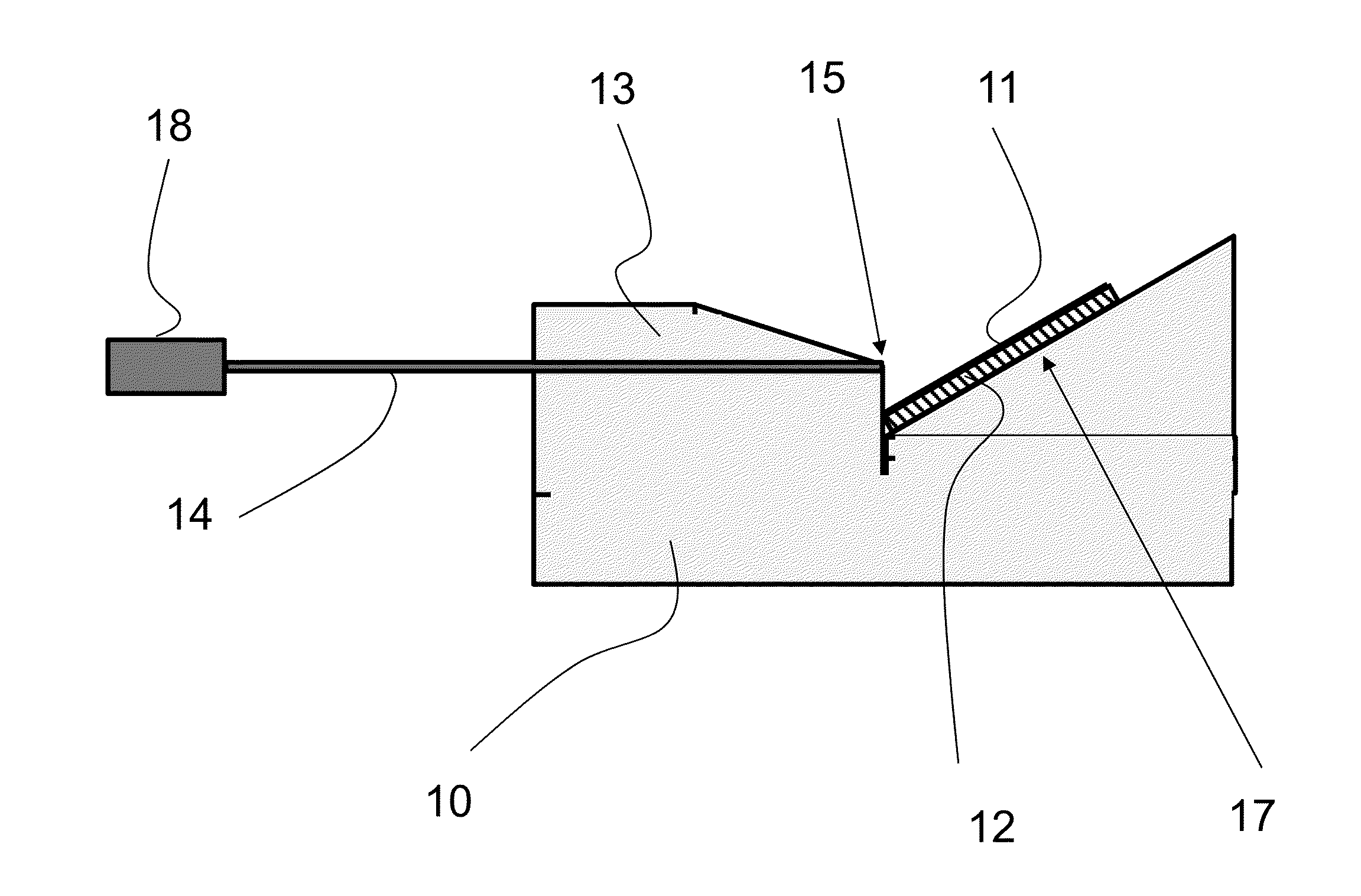
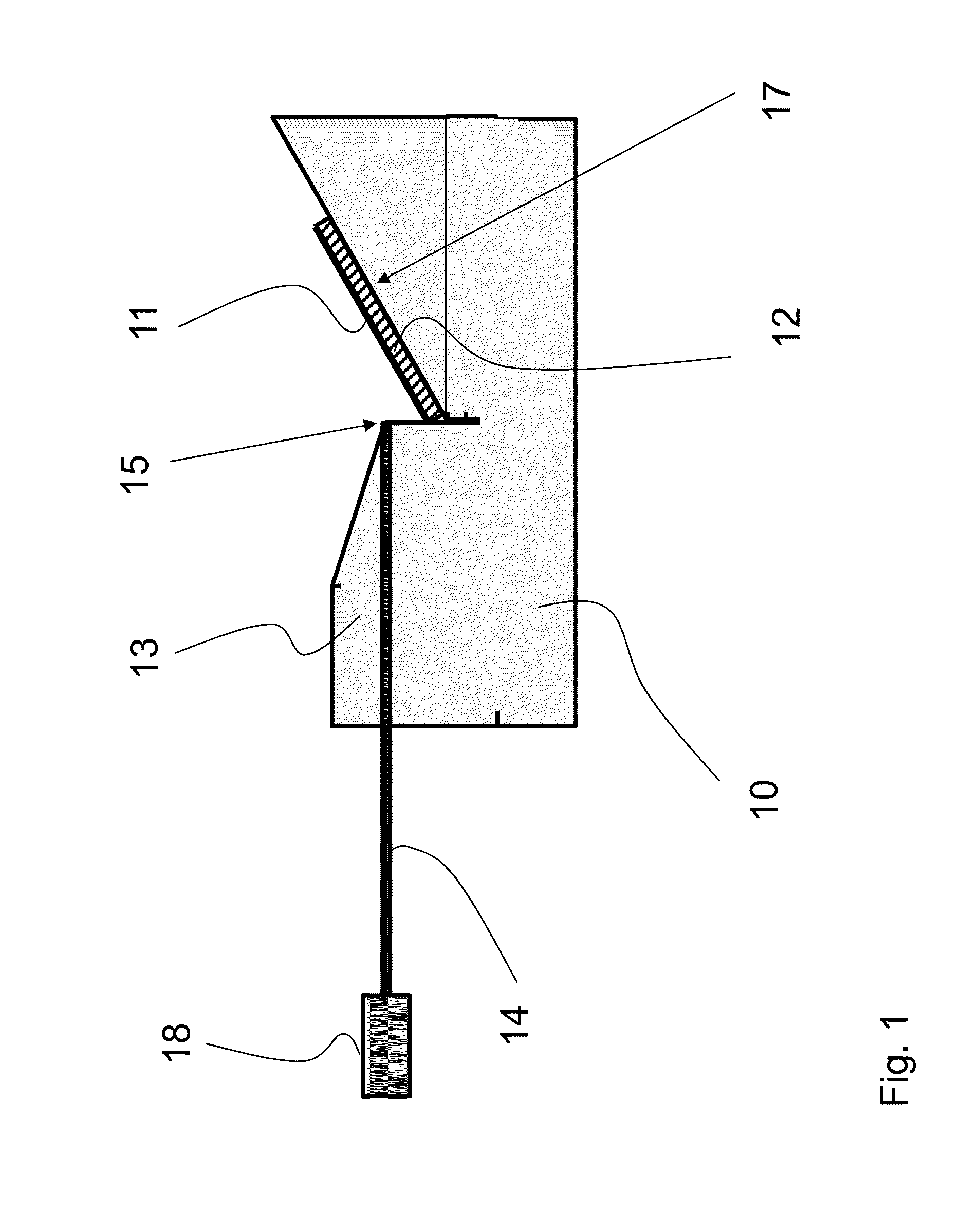
[0147]FIG. 1 is a schematic cross-sectional side view of lighting equipment according to the invention. The excitation light source comprises an optical light conductor which is configured as a fiber optic light conductor 14 and into which electromagnetic radiation of an excitation light source 18 is injected. Light conductor 14 emits the injected electromagnetic radiation as the excitation light at one end 15 thereof towards a conversion medium 11.

[0148]In the region where the conversion medium 11 is fixed, carrier device 10 is provided with a reflective layer 12. This may be a coating on the relevant contact surface 17, for example. It is also possible that a mirror or metallic mirror is provided on the holder. The conversion medium may be securely and / or releasably attached to the carrier devi...


PUM


Abstract

Lighting equipment for generating white light from blue or violet excitation light and converted emitted yellow light is provided. The excitation light is directed at an oblique angle towards a converter that is attached to a carrier device, without the emitted illumination light impinging on the carrier device.

Description

CROSS REFERENCE TO RELATED APPLICATIONS[0001]This application is a continuation of International Application No. PCT / EP2013 / 055232 filed Mar. 14, 2013, which claims the benefit of U.S. Provisional Application Ser. No. 61 / 614,101 filed Mar. 22, 2012 and claims benefit under 35 U.S.C. §119(a) of German Patent Application No. 10 2012 005 660.5 filed Mar. 22, 2012 and European Application No. 12173604.5 filed Jun. 26, 2012, the entire contents of all of which are incorporated herein by reference.BACKGROUND[0002]1. Field of the Disclosure[0003]The present invention relates to lighting equipment for generating high luminance light, in particular white light, which comprises at least one radiation source, a conversion medium, and a carrier device for positioning and fixing the radiation source relative to the conversion medium. The conversion medium is arranged in the optical path of the radiation source and converts at least part of the incident light to a different spectral region, with ...

Claims


Application Information

Patent Timeline
Patent Type & Authority Applications(United States)
IPC IPC(8): F21K99/00F21V8/00
CPCF21K9/56F21K9/52G02B6/0008G02B6/0006B60Q1/00F21K9/61F21K9/64F21S41/125F21S41/13F21S41/16F21S41/176
Inventor WOELFING, BERNDHAGEMANN, VOLKERMEINL, JUERGEN
Owner SCHOTT AG
Why Eureka
Try Eureka