Protective device

a protection device and electromagnetic technology, applied in emergency protective arrangements for limiting excess voltage/current, electrical equipment, multiple-port networks, etc., can solve the problems of the majority of destructive transient energy and the energy that falls below the operational frequency band is often blocked, etc., to achieve the effect of reducing the cost of manufacturing, reducing the cost of operation, and ensuring the quality of the desired electrical energy

Inactive Publication Date: 2015-03-19
KAUFFMAN GEORGE M
View PDF3 Cites 8 Cited by
  • Summary
  • Abstract
  • Description
  • Claims
  • Application Information

AI Technical Summary

Benefits of technology

[0016]It is still another object of the present invention to provide a protective device of the type as described above that is effective in treating transient electromagnetic energy that falls both below and within the operational frequency band without compromising the quality of the desired electrical energy.
[0017]It is yet still another object of the present invention to provide a protective device of the type as described above that has a limited number of parts, is inexpensive to manufacture and is easy to use.

Problems solved by technology

Generally, the lower frequency energy is more destructive to the low-voltage circuit, since the lower frequency energy exists for longer durations and the fundamental frequency of impulses is commonly of the highest spectral content.
For low-voltage circuits connected to a transmission line operating at a frequency range above approximately 10 MHz, it has been found that most of the destructive transient energy falls below the operational frequency band.
This energy that falls below operational frequency band is often blocked using conventional circuit protection techniques.
Although gas discharge tubes can operate over a wide range of frequencies (even well over 1 GHz) and can exhibit very high transient current shunting capabilities, gas discharge tubes respond too slowly to fast rise time transients.
This high-voltage residual pulse passed through the transmission line by the gas discharge tube is substantial enough to permanently damage sensitive electrical equipment.
However, it has been found that quarter wave shunts are ineffective in passing frequencies below 400 MHz, and therefore are not generally utilized in signal transmission applications with a lower operational frequency range.
Similarly, inductors utilized to shunt undesirable energy from the transmission line suffer from certain performance limitations.
Specifically, inductors can only be incorporated into protective devices that operate at frequencies below 100 MHz and, in addition, have been found to experience severe limitations in removing fast rise time transients.
Although both types of shunting protectors described in detail above are commonly utilized in the art to treat electromagnetic energy that falls beneath the operational frequency band, it has been found that the aforementioned shunting protectors are not similarly capable of providing significant attenuation of potentially destructive energy that falls within the operational frequency band.
As a result, destructive transient energy that falls within the operational frequency band poses a significant risk to relatively sensitive, low-voltage circuits coupled to the signal path.
In fact, most conventional protection devices have been found to be incapable of limiting, or otherwise treating, transient energy that falls both below and within the operational frequency band without compromising the quality of the desired electrical energy (i.e., the desired signal that falls within the operational frequency band).

Method used


Image

  • Protective device
  • Protective device
  • Protective device

Examples


second embodiment

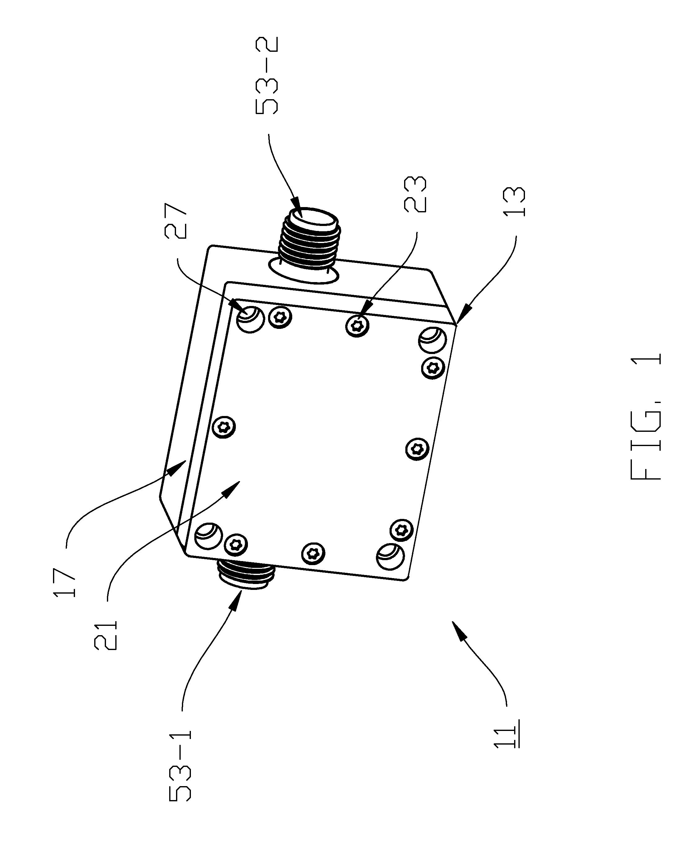
[0070]For instance, referring now to FIG. 4, there is shown a front perspective view of a protective device constructed according to the teachings of the present invention, the protective device being identified generally by reference numeral 111.

[0071]As can be seen, protective device 111 is similar to protective device 11 in that protective device 111 includes an enclosed housing, or casing, 113 into which is disposed an electrical circuit 115, with electrical circuit 115 being designed principally to provide overvoltage protection to a low-voltage circuit.

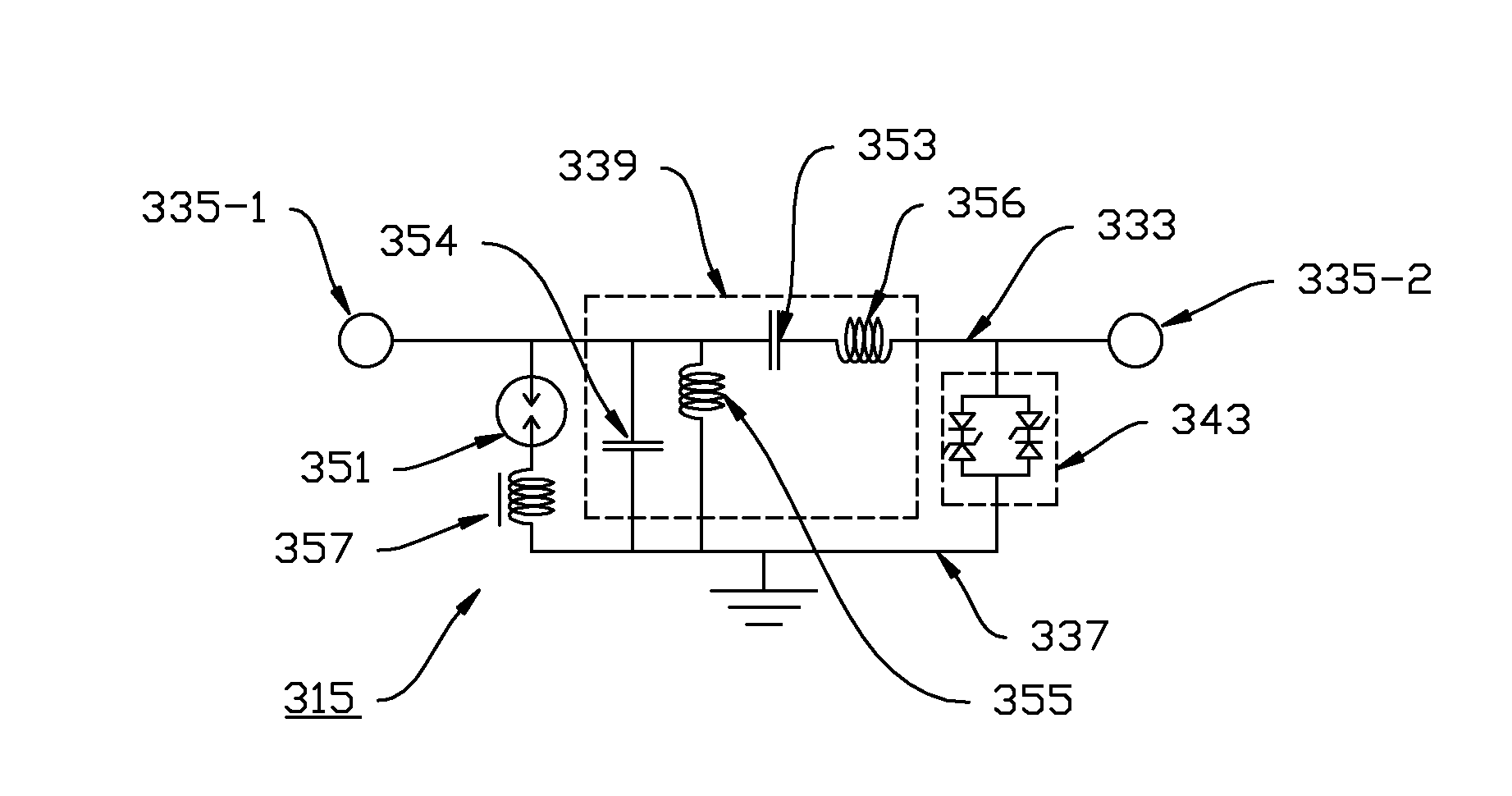
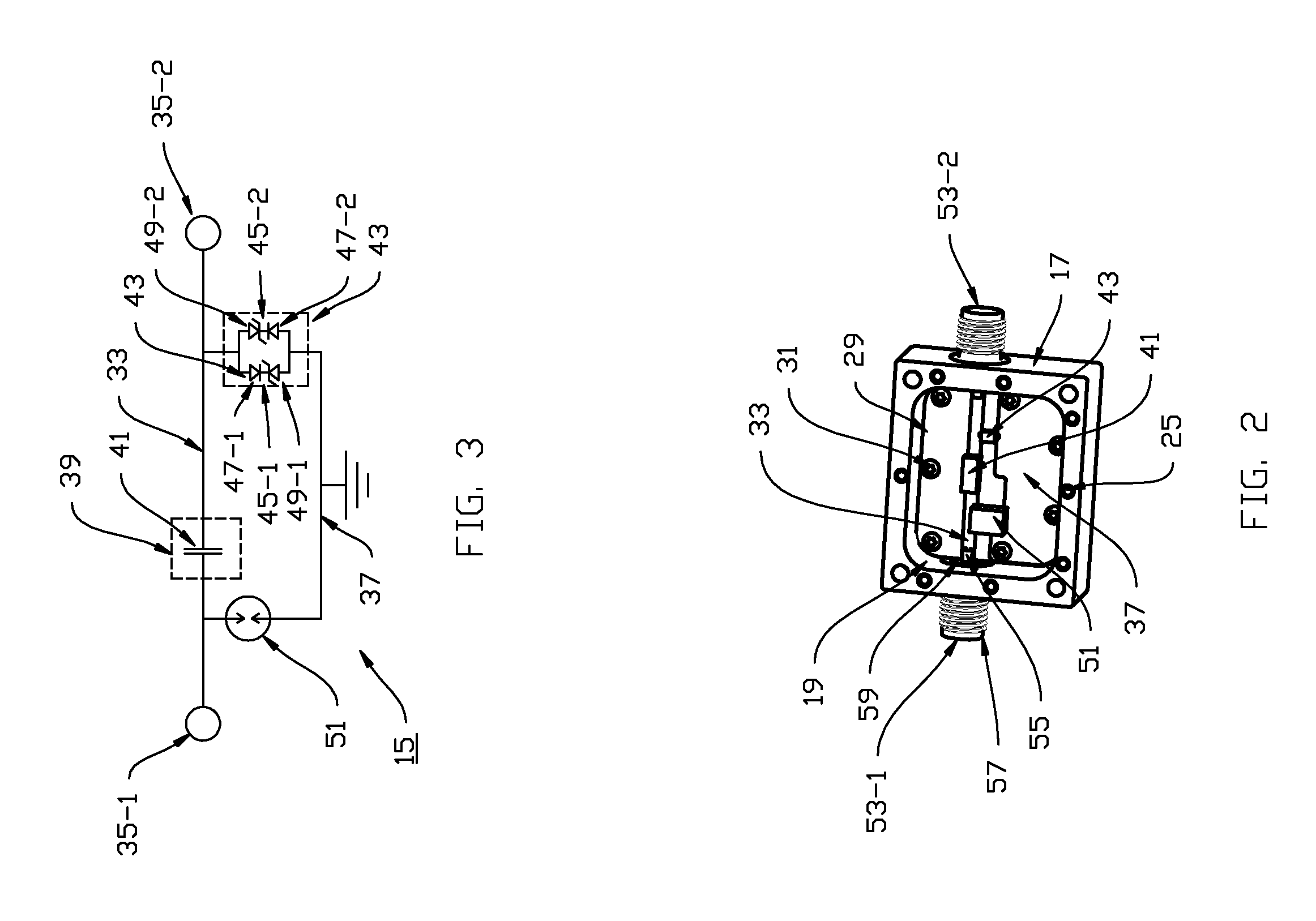
[0072]Referring now to FIG. 5, electrical circuit 115 is similar to electrical circuit 15 in that electrical circuit 115 comprises (i) a transmission line, or through path, 133 that extends in electrical communication between an input, or exposed, terminal 135-1 and an output, or treated, terminal 135-2, (ii) a filter 139 for treating high-voltage, transient electromagnetic impulses that fall primarily below the operational freq...

third embodiment

[0080]For instance, referring now to FIG. 6, there is shown a protective device constructed according to the teachings of the present invention, the protective device being identified generally by reference numeral 211.

[0081]As can be seen, protective device 211 is similar to protective device 111 in that protective device 211 includes an enclosed housing, or casing, 213 into which is disposed an electrical circuit 215, with electrical circuit 215 being designed principally to provide overvoltage protection to a low-voltage circuit.

[0082]Referring now to FIG. 7, electrical circuit 215 is similar to electrical circuit 115 in that electrical circuit 215 comprises (i) a transmission line, or through path, 233 that extends in electrical communication between an input, or exposed, terminal 235-1 and an output, or treated, terminal 235-2, (ii) a filter 239 for treating high-voltage, transient electromagnetic impulses that fall primarily below the operational frequency band, (iii) a diode-...


PUM


Abstract

A device designed to protect low-voltage circuits includes a transmission line for transmitting electromagnetic signals of an operational frequency band, a capacitor located in series on the transmission line, and a diode-based clamping component connecting the transmission line to ground. In use, the capacitor is designed to filter any unwanted transient energy that falls beneath the operational frequency band and the clamping component is designed to limit unwanted transient energy that falls within the operational frequency band. A gas discharge tube (GDT) connecting the transmission line to ground preferably protects low-voltage circuits from higher current threats. An inductive component constructed of a ferrite material, such as a ferrite bead, is connected in series with the GDT. Upon activation of the GDT, the inductive component manages the fall time of the GDT and thereby prevents the output waveform generated in response to GDT activation from shifting into the operational frequency band.

Description

FIELD OF THE INVENTION[0001]The present invention relates generally to devices for transmitting electromagnetic signals of a desired frequency range and, more particularly, to devices for transmitting electromagnetic signals of a desired frequency range that additionally provide overvoltage protection to the transmission line.BACKGROUND OF THE INVENTION[0002]A transmission line, or signal path, is a structure designed to efficiently transmit electromagnetic signals, such as radio frequency (RF) signals, from a signal source to a load. The transmission line formed between the signal source and the load is commonly established using one or more electric devices, such as coaxial cables, connectors and switches.[0003]Electric devices of the type described above are well known in the art and are widely used to transmit electromagnetic signals over 10 MHz with minimum loss and limited distortion. As a result, these types of electric devices are commonly used to transmit and receive signal...

Claims


Application Information

Patent Timeline
Patent Type & Authority Applications(United States)
IPC IPC(8): H02H9/04H03H7/01H02H9/00
CPCH02H9/045H03H7/17H02H9/005H03H7/075
Inventor KAUFFMAN, GEORGE M.
Owner KAUFFMAN GEORGE M
Why Eureka
Try Eureka