Power amplifier circuit

a power amplifier and circuit technology, applied in the direction of rf amplifiers, amplifier modifications to reduce non-linear distortion, amplifiers with field-effect devices, etc., can solve problems such as large phase distortion, and achieve the effect of improving linearity and power efficiency in the power amplifier circui

Active Publication Date: 2015-03-26
MURATA MFG CO LTD
View PDF6 Cites 1 Cited by
  • Summary
  • Abstract
  • Description
  • Claims
  • Application Information

AI Technical Summary

Benefits of technology

[0011]The present invention is made in consideration of the above-mentioned circumstances and an object thereof is to enhance linearity and power efficiency in a power amplifier circuit.
[0013]According to the present invention, it is possible to enhance linearity and power efficiency in the power amplifier circuit.

Problems solved by technology

On the other hand, for example, when the transistor operates at a point B, the phase distortion is large.

Method used


Image

  • Power amplifier circuit
  • Power amplifier circuit
  • Power amplifier circuit

Examples


Embodiment Construction

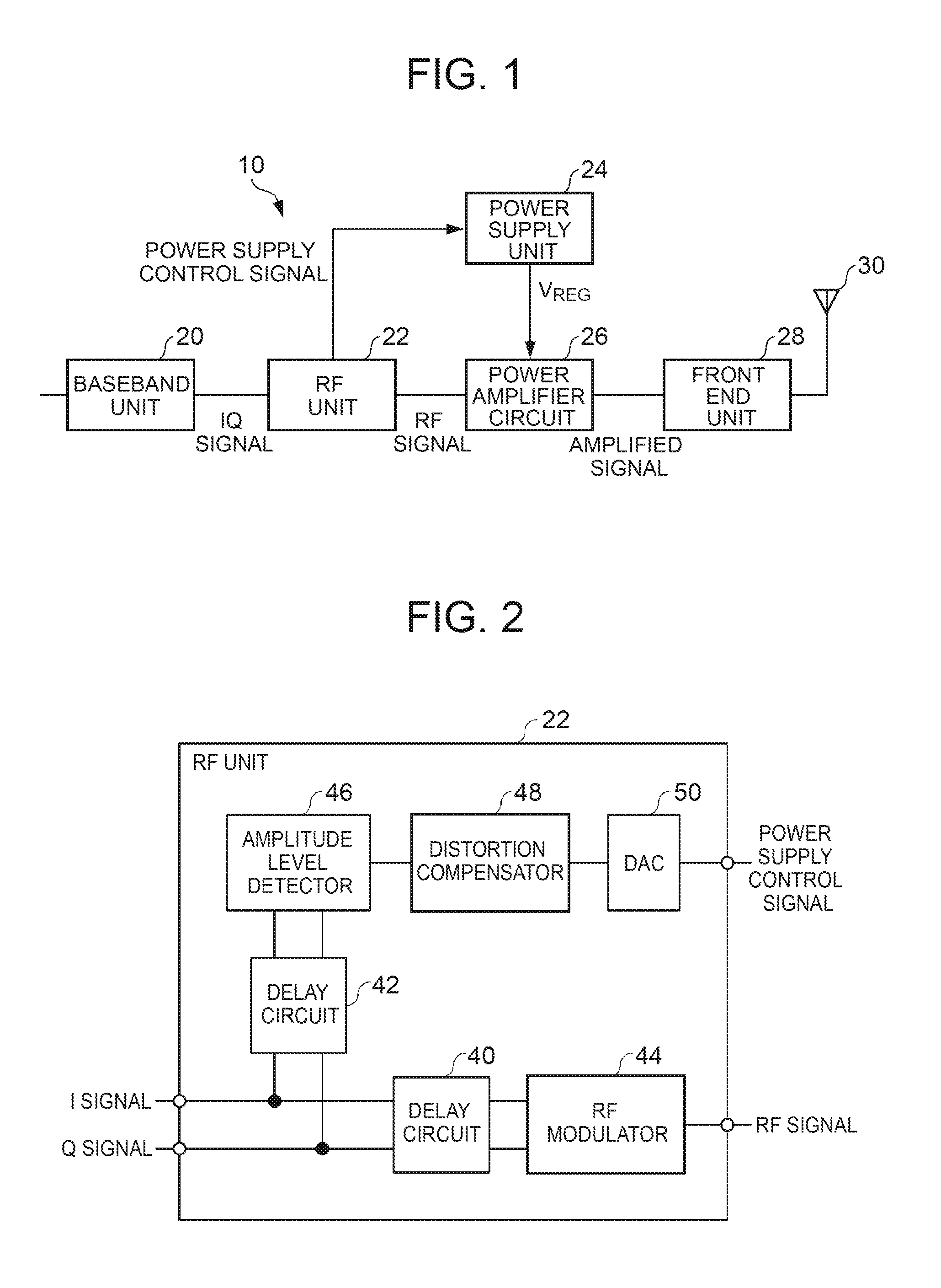
[0034]Hereinafter, an embodiment of the present invention will be described with reference to the accompanying drawings. FIG. 1 is a diagram illustrating a configuration example of a transmitter unit including a power amplifier circuit according to the embodiment of the present invention. The transmitter unit 10 is used to transmit various signals of voice, data, and the like from a mobile communication apparatus such as a mobile phone to a base station. The mobile communication apparatus also includes a receiver unit for receiving signals from a base station but a description thereof will not be made herein.

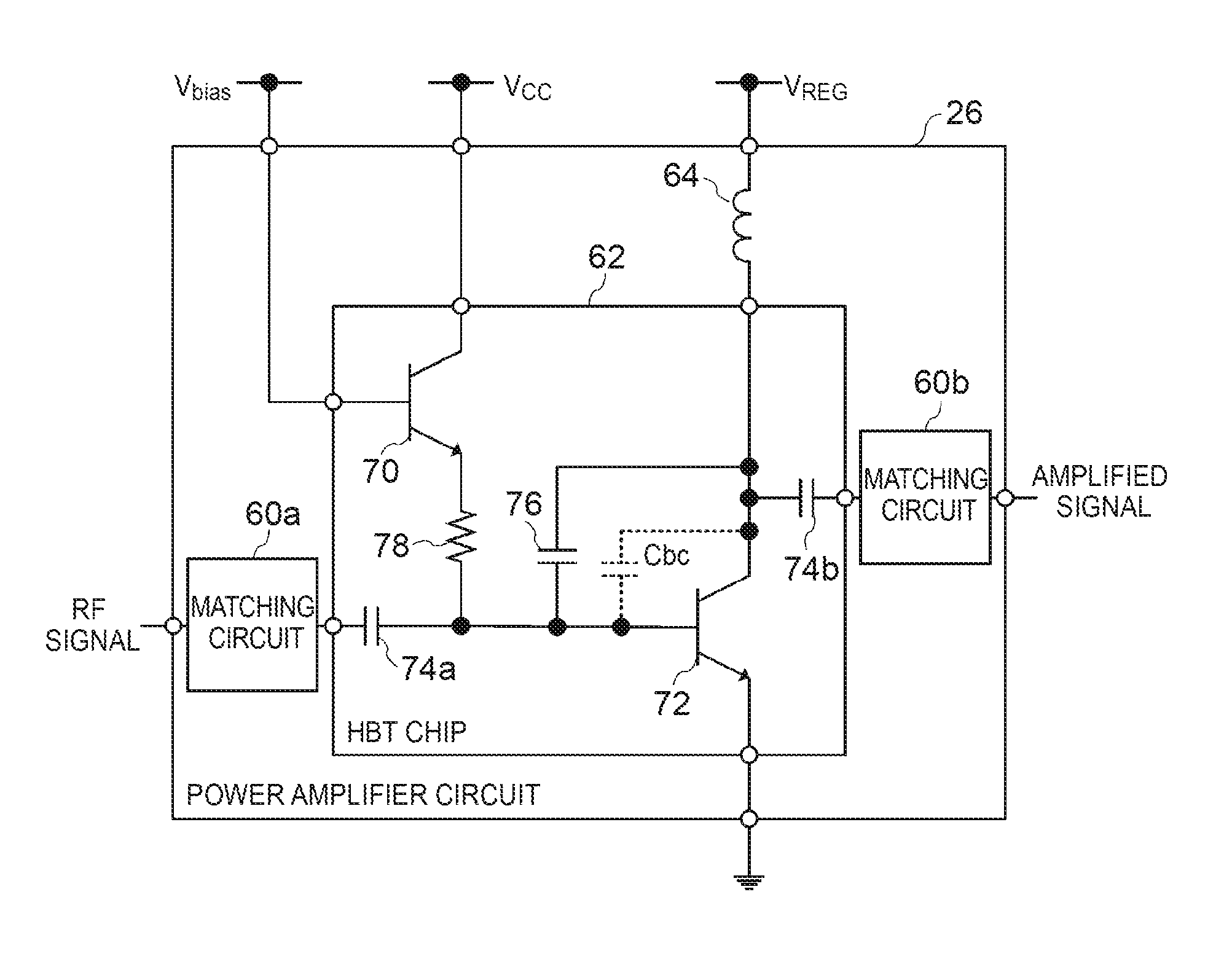
[0035]As illustrated in FIG. 1, the transmitter unit 10 includes a baseband unit 20, a radio frequency (RF) unit 22, a power supply circuit 24, a power amplifier circuit 26, a front end unit 28, and an antenna 30.

[0036]The baseband unit 20 modulates an input signal of voice, data, and the like on the basis of a modulation system such as HSUPA or LTE and outputs a modulation sign...


PUM


Abstract

Linearity and power efficiency in a power amplifier circuit are enhanced. The power amplifier circuit includes a first transistor that amplifies a signal input to the base and that outputs the amplified signal from the collector and a first capacitor that is disposed between the base and the collector of the first transistor and that has voltage dependency of a capacitance value lower than that of a base-collector parasitic capacitance value of the first transistor.

Description

BACKGROUND [0001]1. Technical Field[0002]The present invention relates to a power amplifier circuit.[0003]2. Background Art[0004]In a mobile communication device such as a mobile phone, a power amplifier circuit is used to amplify power of a signal to be transmitted to a base station. In recent years, modulation systems such as a high speed uplink packet access (HSUPA) system, a long term evolution (LTE) system, and an LTE-Advanced system, which are high-speed data communication standards, are employed by mobile phones. In such communication standards, in order to enhance a communication speed, it is important to reduce unevenness in phase or amplitude. That is, high linearity is desirable for the power amplifier circuit. In such communication standards, in order to enhance a communication speed, a range (dynamic range) in which an amplitude of a signal varies may often be broadened. In order to enhance linearity when the dynamic range is broad, a high source voltage is desired and ...

Claims


Application Information

Patent Timeline
Patent Type & Authority Applications(United States)
IPC IPC(8): H03F1/02H03F3/213H03F3/193
CPCH03F1/0205H03F3/193H03F2200/372H03F2200/451H03F3/213H03F1/32H03F3/245H03F2200/18H03F1/0227H03F1/3223H03F1/56H03F3/195H03F2200/222H03F2200/318H03F2200/387H03F2200/411H03F1/02
Inventor ITO, MASAHIROTAKENAKA, KIICHIROTANAKA, SATOSHIMATSUMOTO, HIDETOSHI
Owner MURATA MFG CO LTD
Why Eureka
Try Eureka