Contactless data communication using in-plane magnetic fields, and related systems and methods

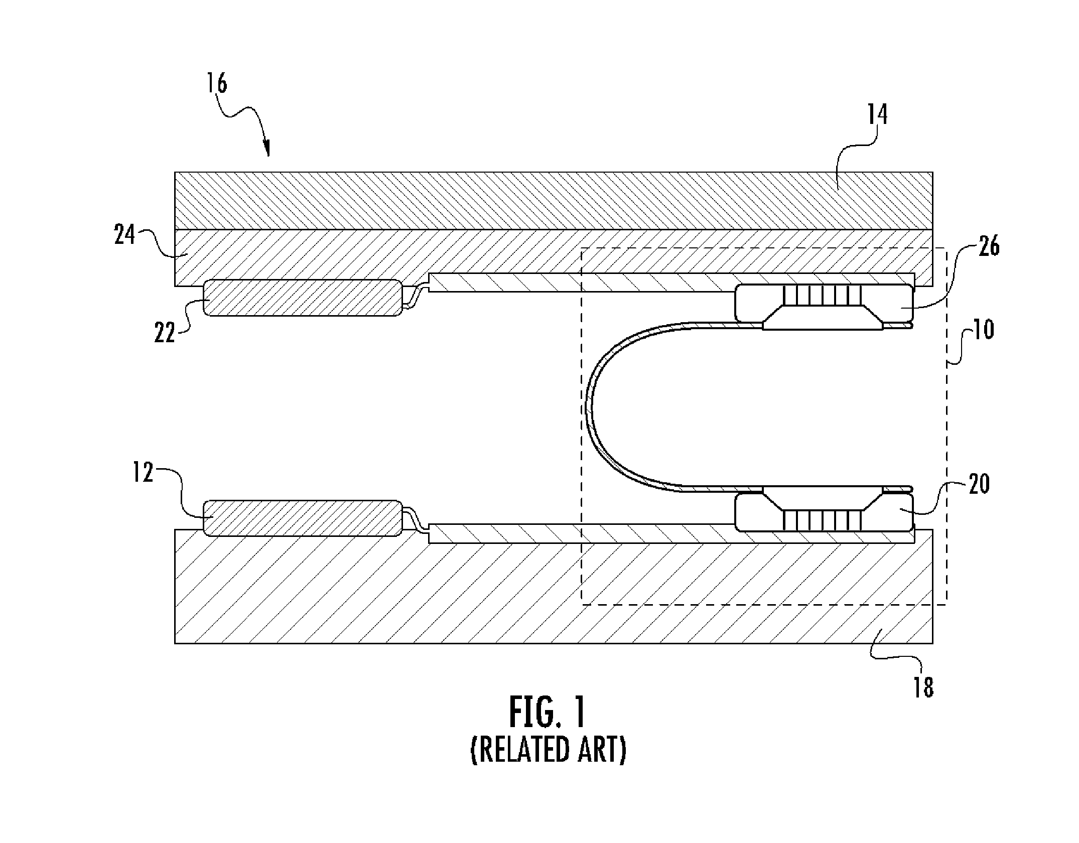
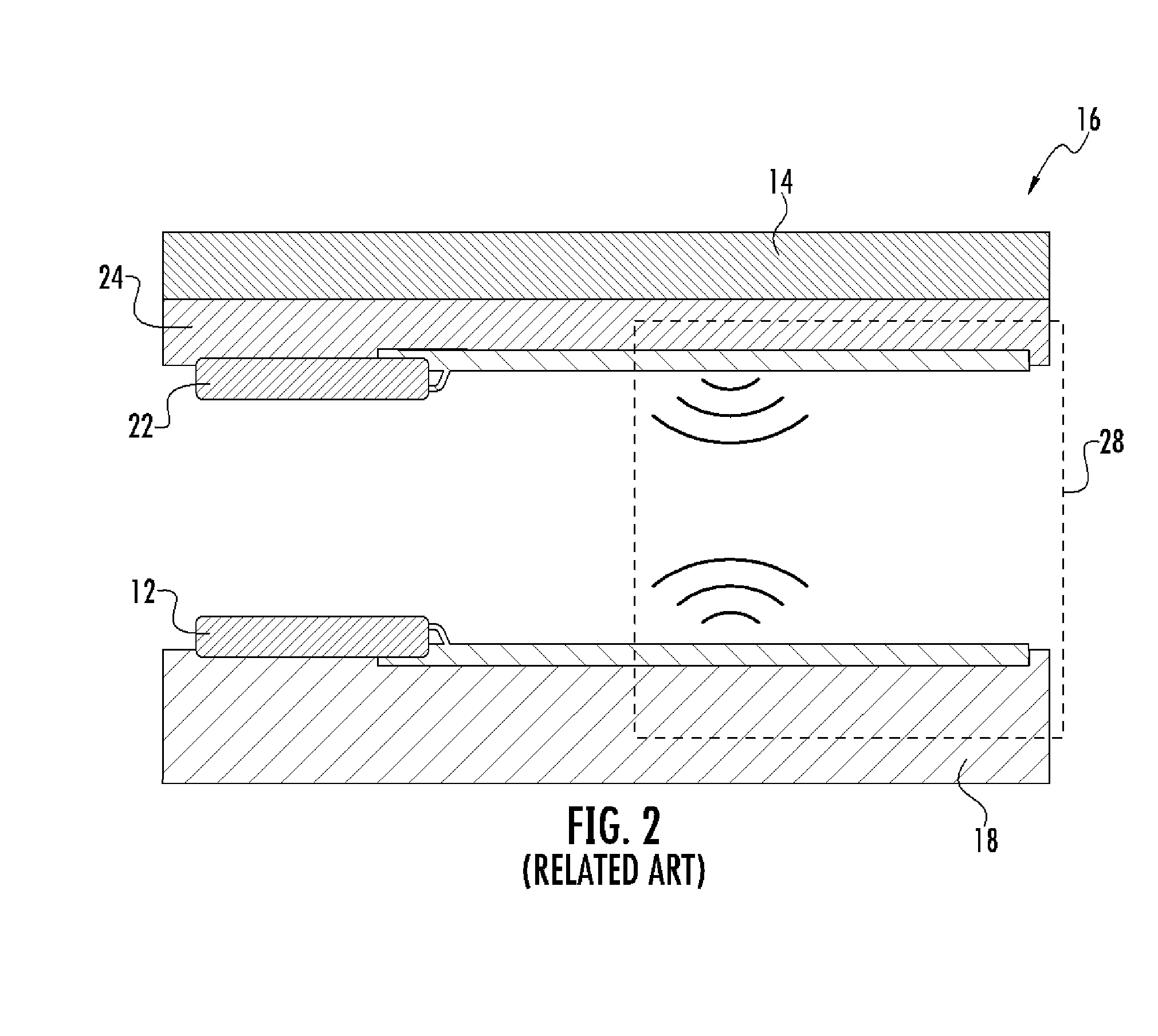
a magnetic field and in-plane technology, applied in the field of contactless data communication systems and methods, can solve the problems of increasing manufacturing costs and assembly lead times, consuming a significant amount of space within the portable electronic device, and the wireline connector b>10/b> may be relatively large, so as to improve the communication range, save power, and increase the data transfer rate

Active Publication Date: 2015-03-26
QUALCOMM INC
View PDF7 Cites 17 Cited by
  • Summary
  • Abstract
  • Description
  • Claims
  • Application Information

AI Technical Summary

Benefits of technology

[0008]Embodiments described herein are related to contactless data communication using in-plane magnetic fields. For example, in-plane magnetic field strength (rather than a rate of strength change as in inductive coupling techniques) may be used to represent data and magnetic tunnel junctions (MTJs) may be used for magnetic field strength sensing (rather than using inductive coils for sensing the change rate of magnetic field strength in inductive coupling contactless communication techniques). Related systems and methods for contactless data communication using in-plane magnetic fields are disclosed herein. In certain embodiments disclosed herein, an in-plane magnetic field-based contactless transmitter is disclosed that includes a substrate, a pair of dipole coils disposed on the substrate, and a drive circuit electrically coupled to the pair of dipole coils. To transmit data to an MTJ receiver disposed on a second substrate, the drive circuit of the magnetic-field based contactless transmitter is configured to drive a first dipole coil of the pair of

Problems solved by technology

However, the wireline connector 10 may be relatively large and consume a significant amount of space within the portable electronic device 16.
The wireline connector 10 may also require manual assembly, thereby increasing manufacturing costs and assembly lead times.
RF wireless connection techniques may also consume more power and have lower data transfer rate capabilities than baseband wireless connection techniques.
High frequency carrier signals used in RF wireless connection techni

Method used


Image

  • Contactless data communication using in-plane magnetic fields, and related systems and methods
  • Contactless data communication using in-plane magnetic fields, and related systems and methods
  • Contactless data communication using in-plane magnetic fields, and related systems and methods

Examples


Embodiment Construction

[0034]With reference now to the drawing figures, several exemplary embodiments of the present disclosure are described. The word “exemplary” is used herein to mean “serving as an example, instance, or illustration.” Any embodiment described herein as “exemplary” is not necessarily to be construed as preferred or advantageous over other embodiments.

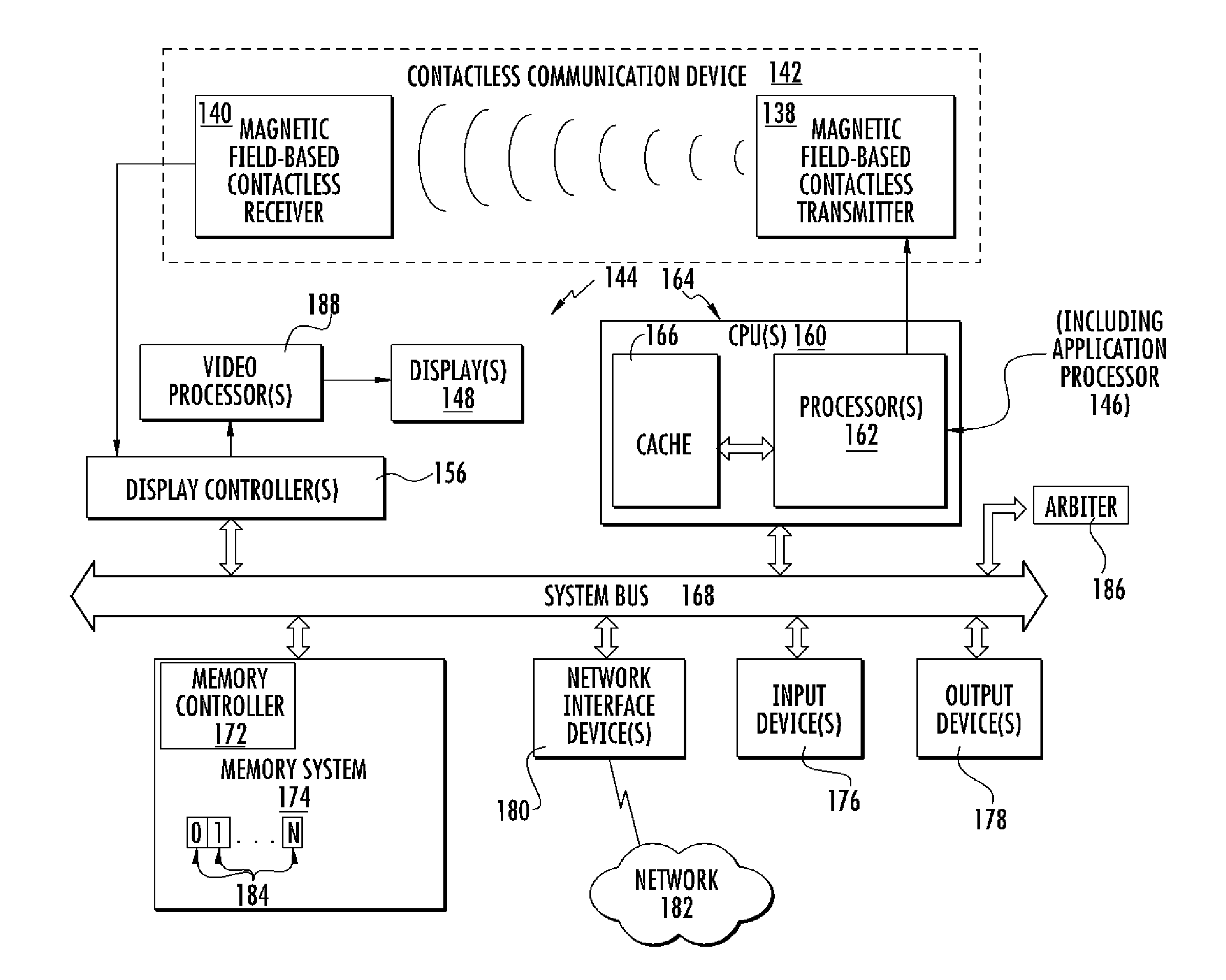
[0035]Embodiments described herein are related to contactless data communication using in-plane magnetic fields. For example, in-plane magnetic field strength (rather than a rate of strength change as in inductive coupling techniques) may be used to represent data and magnetic tunnel junctions (MTJs) may be used for magnetic field strength sensing (rather than using inductive coils for sensing the change rate of magnetic field strength in inductive coupling contactless communication techniques). Related systems and methods for contactless data communication using in-plane magnetic fields are disclosed herein. In certain embodiments disclos...


PUM


Abstract

Embodiments described herein are related to contactless data communication. Related systems and methods for contactless data communication are disclosed herein. For example, a magnetic field-based contactless transmitter is disclosed that includes a substrate, a pair of dipole coils disposed on the substrate, and a drive circuit electrically coupled to the pair of dipole coils. To transmit data to a magnetic tunnel junction (MTJ) receiver disposed on a second substrate, the drive circuit is configured to drive the pair of dipole coils so as to generate a magnetic field in-plane to the MTJ receiver. Data can be transmitted from the magnetic field-based contactless transmitter to the MTJ receiver using the magnetic field.

Description

BACKGROUND[0001]I. Field of the Disclosure[0002]The technology of the disclosure relates generally to systems and methods for contactless data communication.[0003]II. Background[0004]Portable electronic devices, such as mobile phones and tablets in particular, require data communication between internal circuits. For example, a portable electronic device may include data communication components for transferring data between an application processor and a display within the portable electronic device. It may be desirable for these data communication components to provide high data transfer rates between the application processor and the display at desired power consumption levels. Furthermore, since these data communication components consume space in the portable electronic device, it may also be desirable for the data communication components to have a compact form factor. Additionally, it may be desirable to lower costs and lead times required to manufacture and / or assemble porta...

Claims


Application Information

Patent Timeline
IPC IPC(8): G09G3/20H04B5/00H04W4/80
CPCG09G3/2096G09G2370/16H04B5/0087H04B5/0031H04W4/80H10B61/00H10N59/00H10N50/10
Inventor WU, WENQINGGOVINDASWAMY, SENTHIL KUMARMADALA, RAGHU SAGARWANG, PEIYUANYUEN, KENDRICK HOY LEONGHANSQUINE, DAVID JOSEPH WINSTON
Owner QUALCOMM INC
Why Eureka
Try Eureka