Eureka AIR delivers breakthrough ideas for toughest innovation challenges, trusted by R&D personnel around the world.

High harmonic optical generator

a generator and harmonic technology, applied in the field of high harmonic optical generators, can solve the problems of alternating regions of constructive and destructive interference, limited approach to relatively low-order harmonics, and limited techniques to relatively low-order harmonics, and achieve the effect of low generator complexity and low cost manufactur

Active Publication Date: 2015-03-26
LIU LEWIS +2
View PDF3 Cites 7 Cited by
  • Summary
  • Abstract
  • Description
  • Claims
  • Application Information

AI Technical Summary

Benefits of technology

The use of a specific type of optical waveguide allows for the generator to have simple design and low manufacturing costs.

Problems solved by technology

A significant drawback with HHG is that it is inefficient, due to phase-mismatch, which is caused by the different phase velocities of the fundamental driving radiation and the high harmonic radiation generated.
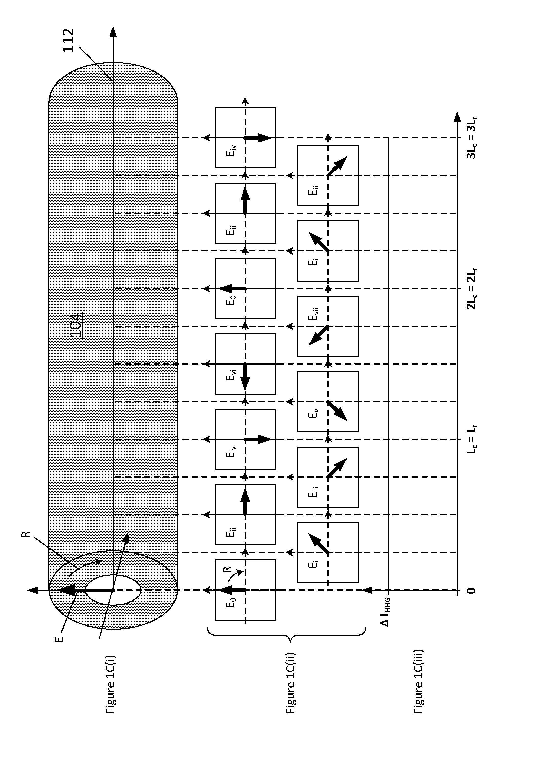
This leads to alternating regions of constructive and destructive interference of the high harmonic radiation within the generating medium (e.g. along an optical waveguide), with the intensity of a high harmonic radiation oscillating back to zero with a period of twice the coherence length (Lc), where the coherence length is defined as the distance over which a π phase difference accumulates between the harmonic radiation and the local phase of harmonic generation from the fundamental radiation.
Although phase-matching techniques are known, and can significantly improve generation efficiency, such techniques are restricted to relatively low-order harmonics.
However, this approach is limited to relatively low-order harmonics since high-order harmonics have short coherence lengths, whereas modulation of the fundamental wave (i.e. the driving beam) occurs over a distance of order the Rayleigh range (e.g. up to a few millimetres); hence, as the period of the modulation is reduced, the modulation of the intensity of the fundamental wave is also reduced.
However, quasi-phase-matching to produce high-order harmonics can be difficult with this technique, since it requires controlled excitation of different waveguide modes, by spatial light modulation techniques.
This method suffers from the disadvantage that additional optical systems, and increased driving laser energy, are required to generate the pulse train.
However, disadvantageously, the generation efficiency of this technique is low, and requires precise micro-machining of the nanoantennae.
Further, the power of the incident driving radiation may be limited due to a low damage threshold of such structures.

Method used


Image

  • High harmonic optical generator
  • High harmonic optical generator
  • High harmonic optical generator

Examples


Embodiment Construction

[0050]Like reference numerals refer to like elements throughout.

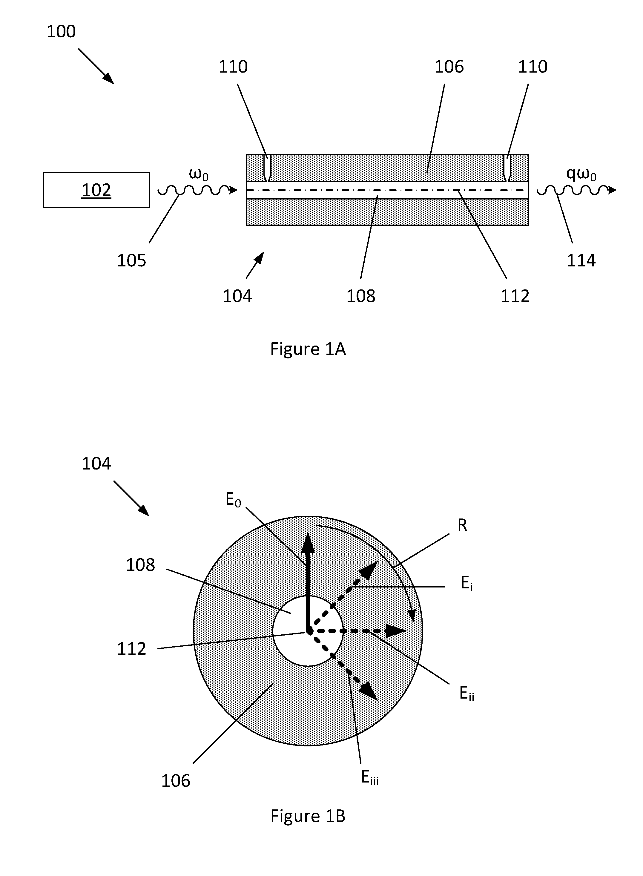
[0051]FIG. 1A shows an optical generator 100 for high harmonic generation comprising a laser 102 and a circularly birefringent hollow core optical waveguide 104. The laser 102 (e.g. which may have a wavelength in the visible or infrared spectrum, such as a pulsed Ti:Sapphire laser having a free space wavelength of 800 nm) is configured to emit linearly polarized radiation 105 of fundamental frequency ω0, which is incident into the optical waveguide 104.

[0052]FIG. 1B shows an end view of the optical waveguide 104, which comprises a cladding layer 106, around a hollow core 108. Gas injection ports 110 are provided for the injection of a gaseous harmonic generation medium (e.g. a noble gas, such as argon) into the hollow core 108, and a vacuum (or low pressure environment) is provided around the optical waveguide 104. However, it will be appreciated that the gas may be provided within the hollow core 108 by other methods. ...


PUM


Abstract

A high harmonic optical generator comprising a laser arrangement for emitting a beam of polarized radiation at a fundamental frequency and an optical waveguide having a hollow core for a gaseous harmonic generation medium for the generation of high harmonics of the fundamental frequency, the optical waveguide having an optical propagation axis along the hollow core, the laser arrangement is configured to couple the beam of polarized radiation along the propagation axis of the hollow core optical waveguide to provide a beam of optical driving radiation for the high harmonic generation, the optical driving radiation having a plane of polarization that rotates about the propagation axis.

Description

[0001]The present invention relates to high harmonic optical generation of polarized radiation by quasi phase-matching within a hollow cored optical waveguide.BACKGROUND[0002]High harmonic generation (HHG) is a technique for the production of coherent extreme ultraviolet (XUV, 120-10 nm) and soft x-ray (SXR, 10-0.1 nm) radiation. For this application, high harmonic generation is considered to relate to the generation of harmonics having free space wavelengths of up to 120 nm. The simple theoretical process for HHG was described by Corkum in three steps: (i) ionization of a ground state atom by high intensity, coherent driving radiation via quantum tunnelling of the electron to the continuum; (ii) propagation of the electron in the continuum under the electromagnetic force of the driving radiation; and (iii) recombination with the ion to release a harmonic photon.[0003]It is known to focus linearly polarized incident light from a pulsed laser into a noble gas (e.g. argon) with a peak...

Claims


Application Information

Patent Timeline
IPC IPC(8): G02B6/10G02F1/095
CPCG02F1/095G02B6/105G02F1/3544G02F1/3558G02F1/365G02F1/383G02F1/3548G02B6/02109G02B6/02328G02B6/03605
Inventor LIU, LEWISO'KEEFE, KEVINHOOKER, SIMON
Owner LIU LEWIS
Why Eureka
Eureka Blog
Learn More