Photonic Lantern Spatial Multiplexers with mode selectivity

Active Publication Date: 2015-03-26
ALCATEL LUCENT SAS
View PDF19 Cites 44 Cited by
  • Summary
  • Abstract
  • Description
  • Claims
  • Application Information

AI Technical Summary

Benefits of technology

[0023]In some embodiments of any of the above apparatus/systems, the respective length of each of the single mode optical waveguides

Problems solved by technology

Although single-mode fiber (SMF) has been the primary transmission medium for high-speed data transmission, the recent exponential growth of data traffic may exhaust

Method used


Image

  • Photonic Lantern Spatial Multiplexers with mode selectivity
  • Photonic Lantern Spatial Multiplexers with mode selectivity
  • Photonic Lantern Spatial Multiplexers with mode selectivity

Examples


Embodiment Construction

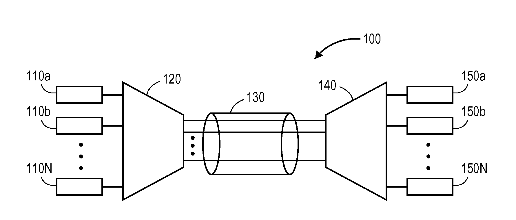
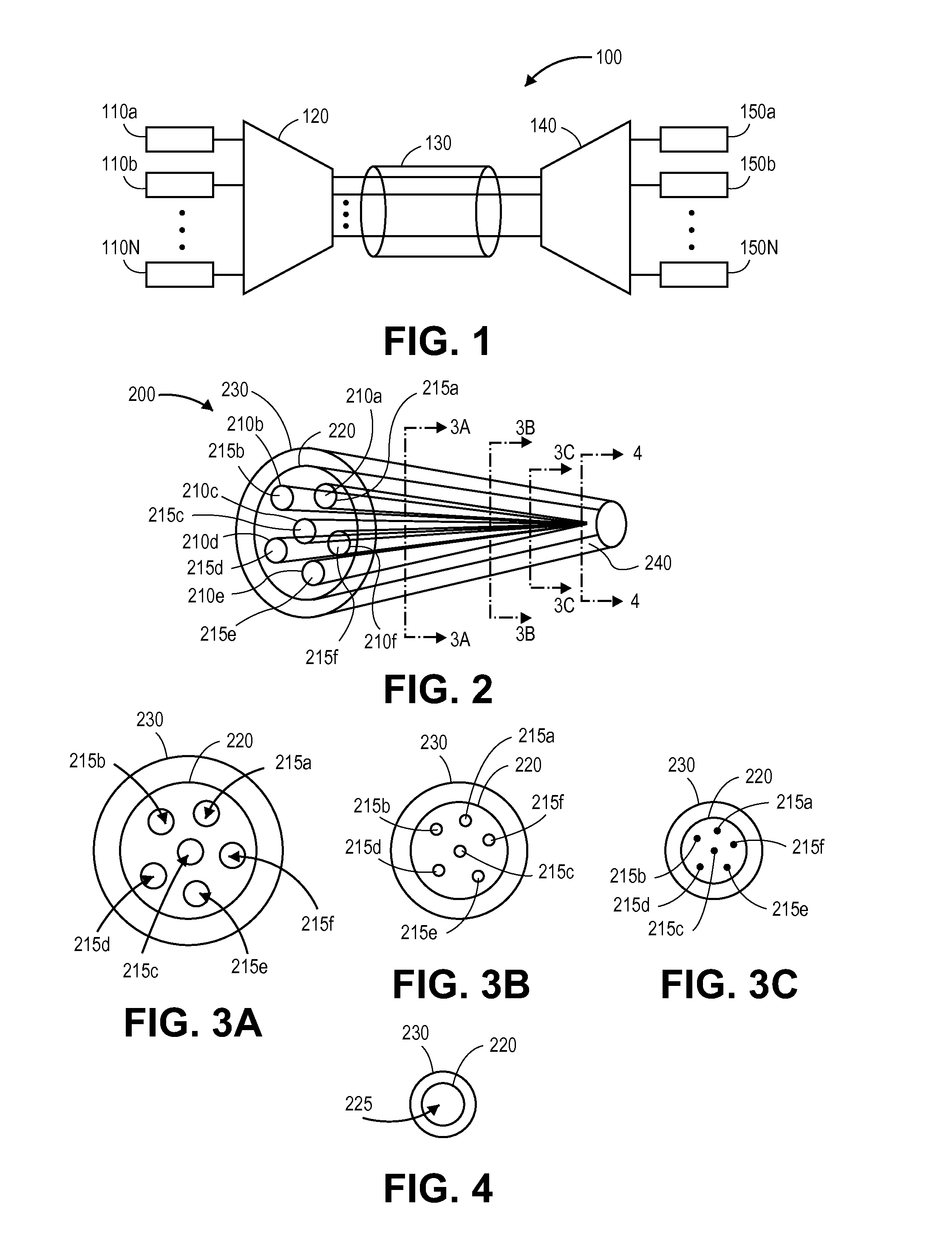
[0034]FIG. 1 illustrates an embodiment of a space-division multiplexing (SDM) optical transmission system 100. The SDM optical transmission system 100 includes a plurality of input single mode optical waveguides 110a, 110b, . . . , 110N, a spatial multiplexer 120, a multimode optical waveguide 130, a spatial demultiplexer 140 and a plurality of output single mode optical waveguides 150a, 150b, . . . , 150N, where N can be up to or greater than 20. The input single mode optical waveguides 110a, 110b, . . . , 110N are coupled to the multimode optical waveguide 130 via the spatial multiplexer 120. In addition, the output single mode optical waveguides 150a, 150b, . . . , 150N are coupled to the multimode optical waveguide via the spatial demultiplexer 140.

[0035]Each of the input / output single mode optical waveguides 110a, 110b, . . . , 110N and 150a, 150b, . . . , 150N guides a single transverse mode (or propagation path) of light along a length thereof, whereas the multimode optical w...


PUM


Abstract

A photonic lantern spatial multiplexer that provides mode selectivity includes a multimode optical waveguide and a plurality of single mode optical waveguides. The single mode cores of the single mode optical waveguides merge with the multimode core of the multimode optical waveguide. At least two of the single mode cores have different respective single mode effective refractive indexes.

Description

CROSS-REFERENCE TO RELATED PATENTS[0001]Not Applicable.STATEMENT REGARDING FEDERALLY SPONSORED RESEARCH OR DEVELOPMENT[0002]Not Applicable.INCORPORATION-BY-REFERENCE OF MATERIAL SUBMITTED ON A COMPACT DISC[0003]Not applicable.BACKGROUND[0004]1. Technical Field[0005]This invention relates generally to optical transmission systems and in particular, but not exclusively, to space-division multiplexing in optical transmission systems.[0006]2. Description of Related Art[0007]Although single-mode fiber (SMF) has been the primary transmission medium for high-speed data transmission, the recent exponential growth of data traffic may exhaust the available capacity of SMF in the near future. To overcome the capacity limitations experienced by SMF, space-division multiplexing (SDM) transmission systems based on multi-core fiber (MCF) or multi-mode fiber (MMF) are being developed.[0008]In a typical SDM transmission system, optical signals are generated and launched onto respective SMFs. Mode mu...

Claims


Application Information

Patent Timeline
IPC IPC(8): G02B6/14
CPCG02B6/14G02B6/02042G02B6/0288G02B6/2821H04J14/04
Inventor FONTAINE, NICOLAS K.RYF, ROLAND
Owner ALCATEL LUCENT SAS
Why Eureka
Try Eureka