
Electrically Heated Catalyst for a Compression Ignition Engine

a technology of ignition engine and catalyst, which is applied in the direction of metal/metal-oxide/metal-hydroxide catalyst, physical/chemical process catalyst, and catalyst, which takes a significant amount of time to heat up to their effective operating temperature, and platinum group metals such as platinum and palladium are expensive constituents of emissions control devices, so as to achieve good oxidative activity

Active Publication Date: 2015-03-26
JOHNSON MATTHEY PLC
View PDF30 Cites 18 Cited by
  • Summary
  • Abstract
  • Description
  • Claims
  • Application Information

AI Technical Summary

Benefits of technology

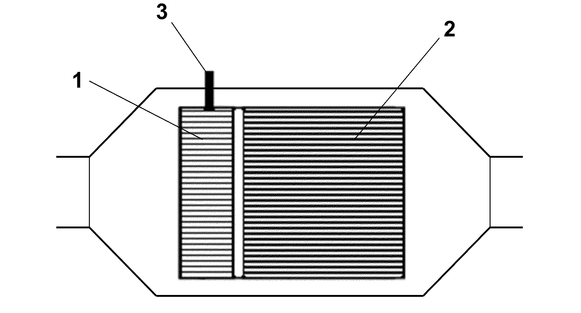
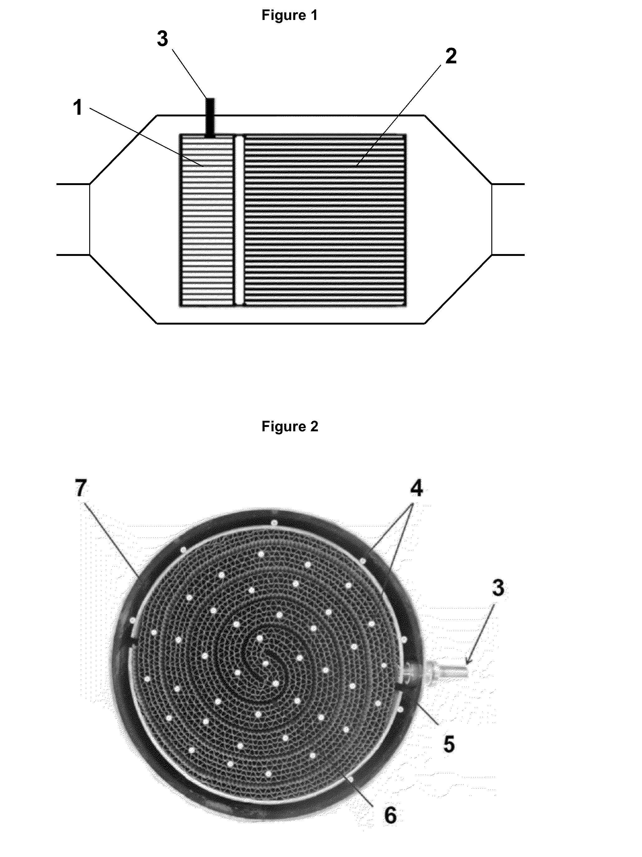
This patent relates to a technology that helps reduce emissions from engines by quickly heating up a catalyst to its effective operating temperature, which can oxidize carbon monoxide and hydrocarbons. The technology uses an electrically heated substrate coated with a composition containing a platinum group metal (PGM) to quickly heat up the exhaust system after a cold start. This results in a reduction of emissions directly from the engine compared to conventional catalysts. Additionally, the technology maintains the temperature of the catalyst when exhaust gas temperatures decrease, such as during idling or engine stop-start modes. The presence of a catalytically active coating on the substrate also reduces power consumption.

Problems solved by technology

However, such catalysts take a significant amount of time to heat up to their effective operating temperature (e.g. light off temperature) from a cold start.
Platinum group metals, such as platinum and palladium, are expensive constituents of emissions control devices.

Method used


Image

  • Electrically Heated Catalyst for a Compression Ignition Engine
  • Electrically Heated Catalyst for a Compression Ignition Engine

Examples


example 1

[0152]Coating the First, Electrically Heatable Substrate (Coating 1)

[0153]Alumina powder was slurried in water and milled to a d90 <20 micron. Soluble salts of platinum and palladium were added and the slurry stirred to homogenise. The resulting washcoat was applied using established coating techniques to the open face of the first substrate with 160 cpsi. The coating was subsequently dried.

[0154]Coating the Second Substrate (Coating 2)

[0155]A second washcoat was prepared using the same method that was used for Coating 1 except that the slurry had a higher content of alumina. This coating was applied using established coating techniques to the open face of the second substrate with 600 cpsi. The coating was subsequently dried and the whole part was calcined at 500° C.

[0156]The final coating loading on the first substrate was 1.3 g in−3. The final coating loading on the second substrate was 1.8 g in−3.

example 2

[0157]Coating the First, Electrically Heatable Substrate (Coating 3)

[0158]A silica-alumina powder was slurried in water and milled to a d90 <20 micron. Soluble salts of platinum and palladium were added and the slurry stirred to homogenise. The resulting washcoat was applied using established coating techniques to the open face of the first substrate with 160 cpsi. The coating was subsequently dried.

[0159]Coating the Second Substrate (Coating 4)

[0160]A second washcoat was prepared using the same method that was used for Coating 3 except that the slurry had a higher content of alumina. This coating was applied using established coating techniques to the open face of the second substrate with 600 cpsi. The coating was subsequently dried and the whole part calcined at 500° C.

[0161]The final coating loading on the first substrate was 2.0 g in−3. The final coating loading on the second substrate was 2.8 g in−3.


PUM

PropertyMeasurementUnit
lengthaaaaaaaaaa
specific heat capacityaaaaaaaaaa
lengthaaaaaaaaaa

Abstract

An emissions control device for a compression ignition engine is described. The emissions control device comprises: (a) a first catalyst comprising an electrically heatable substrate and a first composition disposed on the electrically heatable substrate, wherein the first composition comprises alumina and a first platinum group metal (PGM); and (b) a second catalyst comprising a substrate and a second composition disposed on the substrate, wherein the second composition comprises alumina and a second platinum group metal (PGM); wherein the loading of the first composition is less than the loading of the second composition.

Description

CROSS REFERENCE TO RELATED APPLICATIONS[0001]This application claims priority benefit to Great Britain Patent Application No. 1316790.3 filed on Sep. 20, 2013, which is incorporated herein by reference.FIELD OF THE INVENTION[0002]The invention relates to an emissions control device for a compression ignition engine, such as a diesel engine. The invention also relates to an exhaust system for a compression ignition engine and a vehicle comprising a compression ignition engine.BACKGROUND TO THE INVENTION[0003]Compression ignition engines produce an exhaust emission that generally contains at least four classes of pollutant that are legislated against by inter-governmental organisations throughout the world: carbon monoxide (CO), unburned hydrocarbons (HCs), oxides of nitrogen (NOx) and particulate matter (PM). Emissions control devices known as oxidation catalysts (or diesel oxidation catalysts) are commonly used to treat carbon monoxide (CO) and hydrocarbons (HCs), including the vola...

Claims


Application Information

Patent Timeline
Patent Type & Authority Applications(United States)
IPC IPC(8): B01J23/44B01J21/12B01J21/04B01J23/42
CPCB01J23/44B01J21/04B01J21/12B01J23/42F01N3/103F01N3/105F01N3/2006F01N3/2013F01N2330/02F01N13/0097F01N13/0093F01N3/10F01N3/2026Y02A50/20Y02T10/12B01D53/9477
Inventor CHIFFEY, ANDREW FRANCISGOODWIN, JOHN BENJAMIN
Owner JOHNSON MATTHEY PLC
Learn More