
Method and devices for time and frequency synchronization

a time-frequency technology, applied in the field of time and frequency synchronization, can solve the problems of more difficult time/frequency transfer, scope of telecom synchronization, and propagation of mostly wandering up to the receiver clock signal

Inactive Publication Date: 2015-04-02
KHALIFA UNIV OF SCI & TECH & RES KUSTAR +2
View PDF4 Cites 27 Cited by
  • Summary
  • Abstract
  • Description
  • Claims
  • Application Information

AI Technical Summary

Benefits of technology

This patent text describes a method and system for synchronizing the frequency and time of a slave clock in a slave device with a master clock in a master device over a network. The method involves exchanging timing messages and recording timestamps, estimating the offset and skew of the slave clock relative to the master clock using an exponentially weighted recursive least squares algorithm, and adjusting the frequency and time of the slave clock to align with the master clock. The system includes a master device with a master clock, a slave device with a slave clock, and a network connecting them. The technical effects include improved synchronization between devices and better operational performance of network-connected devices.

Problems solved by technology

Even though time synchronization for IT computing systems and sensor networks have the same underlying concepts, these systems have different application requirements, protocols, architectures, and implementation goals and therefore considered completely out of scope of telecom synchronization.
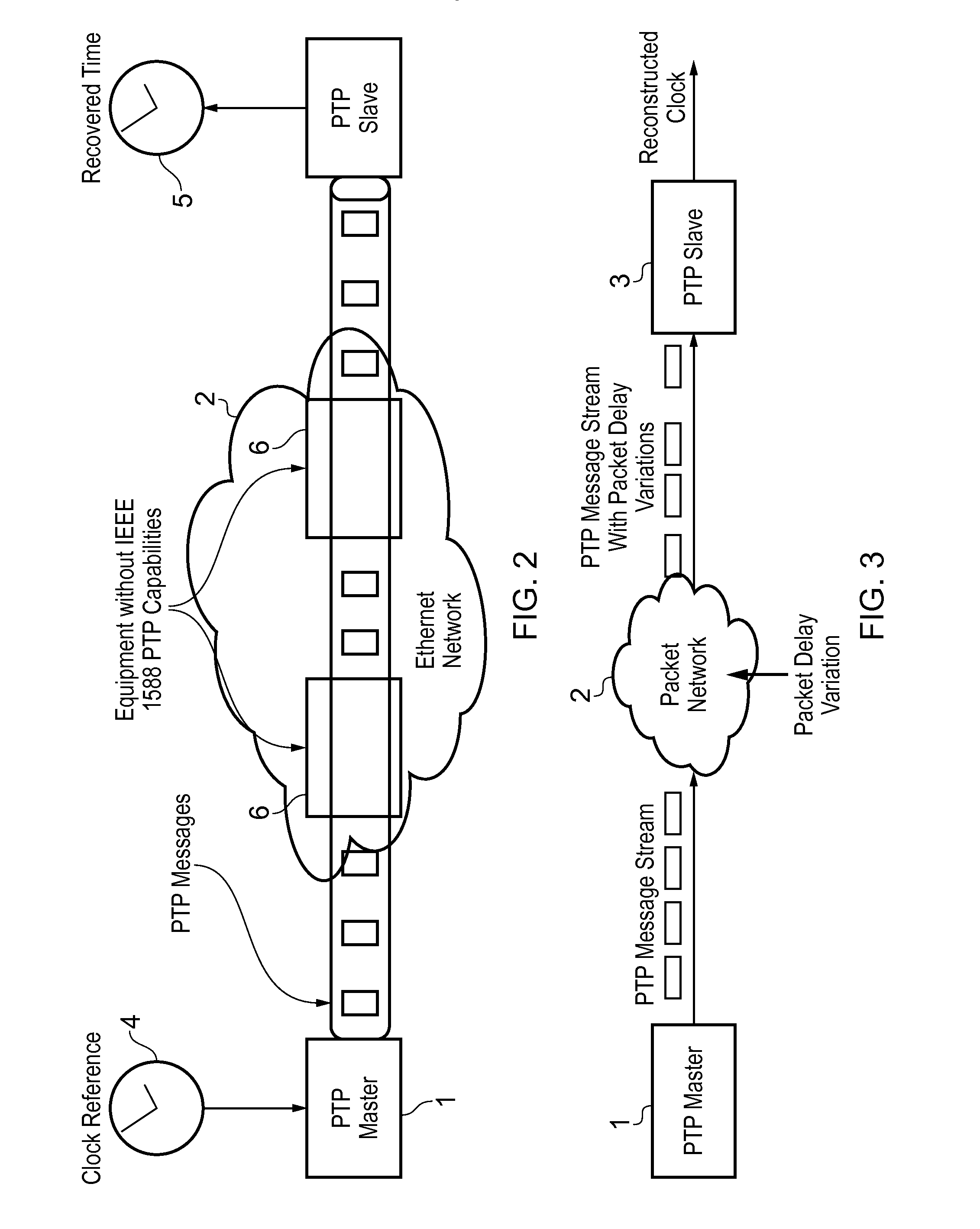
However, the presence of packet delay variation (PDV) and packet losses affects the performance of the clock estimation / compensation process, making the transmitter clock appear faster or slower than it actually is, and ultimately, causing the propagation of mostly wander up to the receiver clock signal.
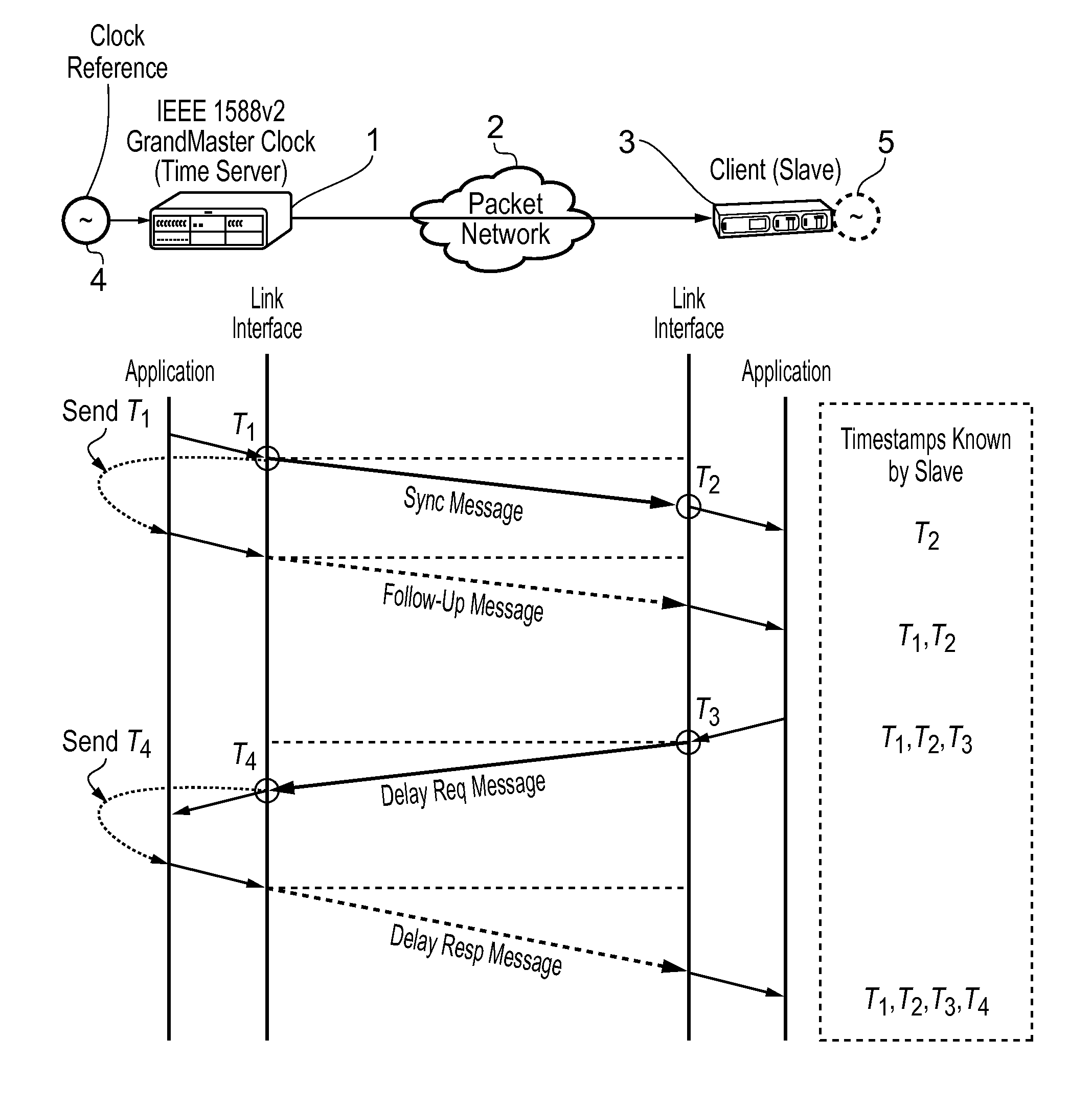
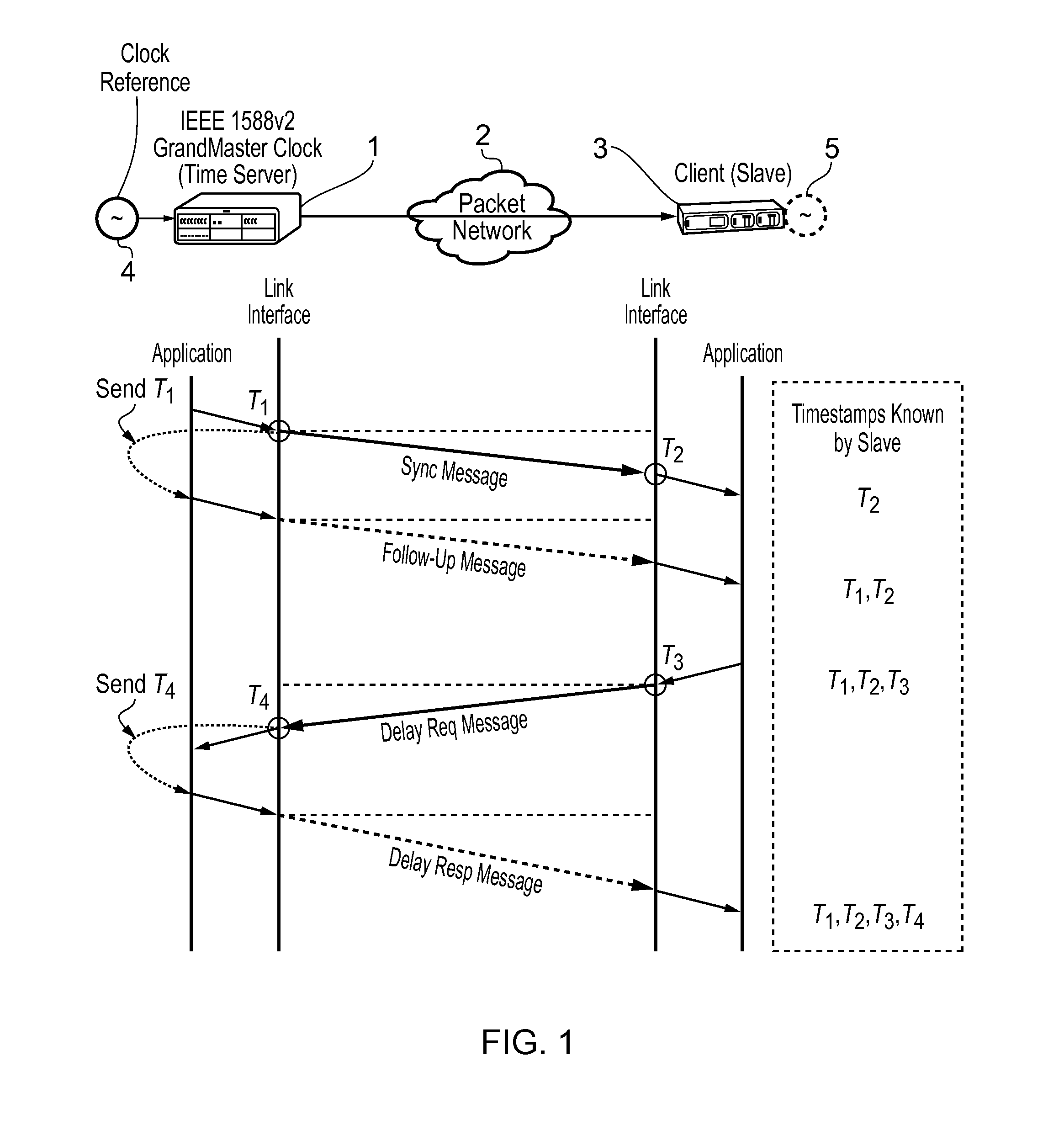
Compared to the other methods (e.g., using hop-by-hop Boundary Clocks or Transparent Clocks), time / frequency transfer here is more challenging because the slave 3 is exposed to all the PDV generated by the intermediate packet network 2 (FIG. 3 and FIG. 4).
The PDV inherent in packet networks is a primary source of clock noise.

Method used


Image

  • Method and devices for time and frequency synchronization
  • Method and devices for time and frequency synchronization
  • Method and devices for time and frequency synchronization

Examples


Embodiment Construction

[0036]Accordingly, at their broadest, methods of the present invention provide for synchronization of the frequency and time of a slave clock using a recursive least squares algorithm.

[0037]A first aspect of the present invention provides a method of synchronising the frequency and time of a slave clock in a slave device to a master clock in a master device, wherein the master device and the slave device are connected by a network, the method including the steps of: exchanging, between the master device and the slave device, timing messages and timestamps which are: the time of sending of timing messages from the master device according to the master clock; the time of receipt of said timing messages according to the slave clock; the time of sending of said timing messages according to the slave clock; and the time of receipt of said timing messages according to the master clock; estimating the offset and skew of the slave clock compared to the master clock by applying an exponentia...


PUM


Abstract

This invention relates to methods and devices for time and frequency synchronization, especially over packet networks using, for example, the IEEE 1588 Precision Time Protocol (PTP). Timing protocol messages are exposed to artifacts in the network such as packet delay variations (PDV) or packet losses. Embodiments of the invention provide a recursive least squares mechanism for clock offset and skew estimation. A major potential advantage of such estimation is that it does not require knowledge of the statistics of the measurement noise and process noise. An implementation using a digital phase locked loop based on direct digital synthesis to provide both time and frequency signals for use at the slave (time client) is also provided.

Description

FIELD OF THE INVENTION[0001]The present invention relates to methods and devices for time and frequency synchronization. It is particularly, but not exclusively, concerned with time and frequency synchronization over packet networks using, for example, the IEEE 1588 Precision Time Protocol (PTP).BACKGROUND OF THE INVENTION[0002]Mobile networks fall into two categories, Frequency Division Duplexing (FDD), which uses two separated frequency bands to transmit / receive, and Time Division Duplexing (TDD), which transmits and receives on a single frequency band. Time synchronization (in addition to frequency synchronization) is needed for LTE-TDD, WiMAX TDD, CDMA networks (popular in North America), TD-CDMA and TD-SCDMA, while only frequency synchronization is required for LTE-FDD, GSM (global system for mobile communications), W-CDMA, and other wireless technologies. Even with the use of LTE-FDD, new LTE mobile services such as network MIMO and location-based services will demand accurate...

Claims


Application Information

Patent Timeline
Patent Type & Authority Applications(United States)
IPC IPC(8): H04J3/06
CPCH04J3/0661H04J3/0667
Inventor AWEYA, JAMES
Owner KHALIFA UNIV OF SCI & TECH & RES KUSTAR
Learn More